2 applying signals to the connector module – Nevion WOS-2 User Manual
Page 9
WOS-2
Rev. H
nevion.com | 9
5. When inserting the new module for the first time, make sure that the connector on
the PCB aligns with connector on the back plane.
NOTE: The PCB shall enter the back plane connector easily
6. If a module is placed in the position left to the module (as seen from the rear), a
rubber plug must replace the spring-loaded plastic shield of the fiber adapter.
4.1.2 Applying signals to the connector module
The optical connection is an SC/UPC connector with a return loss better than 40dB typ.
According to SMPTE specifications, the return loss shall be better than 26 dB.
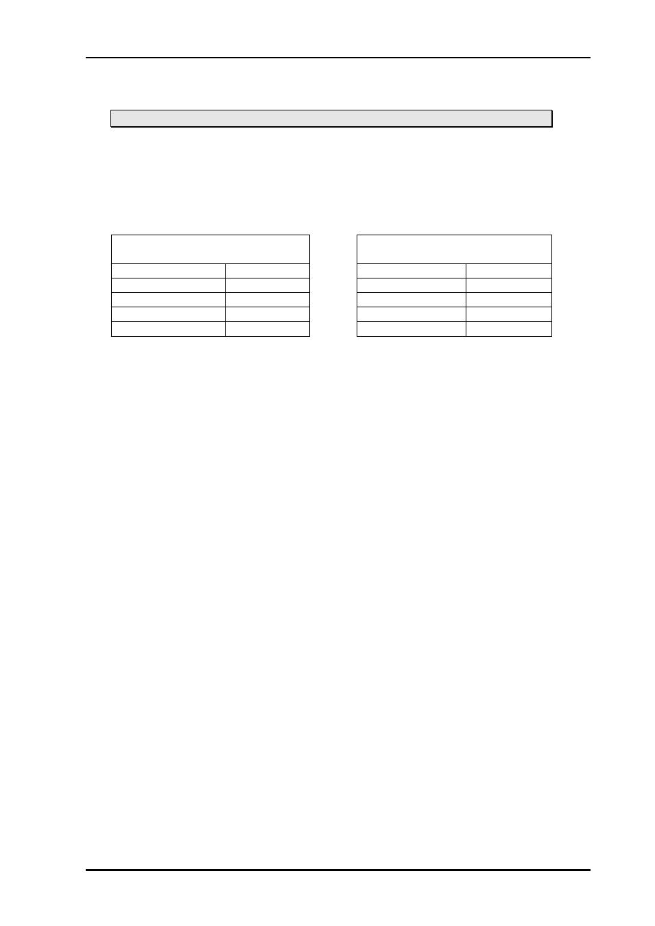
WOS-2x1 and WOS-2x1L:
WOS-2x2 and WOS-2x2L:
Conn. mod. port
Switch port
Conn. mod. port
Switch port
OPT 1
Not used
OPT 1
Input 1
OPT 2
Output 1(*)
OPT 2
Output 1
OPT 3
Common
OPT 3
Input 2
OPT 4
Output 2(*)
OPT 4
Output 2
(*) Can also be used as input port, meaning that both 2x1 and 1x2 functionality
can be implemented.