4 connections, 1 connector module, 4connections – Nevion WOS-2 User Manual
Page 8
WOS-2
Rev. H
nevion.com | 8
4
Connections
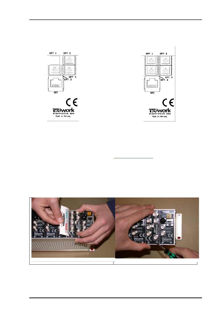
4.1 Connector module
Overview of the WOS-C1 connector module for 2x1
switch configuration
Overview of the WOS-2x2 connector module for 2x2
switch configuration
4.1.1 Field Modification Instruction, replacement of back plane and PCB.
This Field Modification Instruction from Nevion shows how to replace the back plane on the
Flashlink frame. For questions please contact
1. If there is installed a board in the actual slot from earlier, carefully remove this board
first.
2. Carefully remove all 4 screws (2 screws if a blank back plane is mounted) from the
back plane to be replaced.
3. Insert the new back plane carefully. Use your business card (or another suitable
card), as shown in figure below, to avoid that the EMC shield is damaged when
inserting the new back plane.
4. Before tightening the screws, use one of your fingers to force the back plane to the
bottom of the frame as shown above. Tighten the 2 screws at the bottom at the back
plane first. This is to avoid mismatch between the connector on the back plane and
the PCB.