5 module status, 1 gpi alarm, Module status outputs – Nevion LB-OE Rev.E User Manual
Page 10: 1 gpi alarm – module status outputs
LB-OE
Rev. E
nevion.com | 10
5 Module status
The status of the module can be monitored in three ways.
1. GYDA System Controller (optional).
2. GPI at the rear of the sub-rack.
3.
LED’s at the front of the sub-rack.
Of these three, the GPI and the LED’s are mounted on the module itself, whereas the
GYDA System Controller is a separate module giving detailed information on the card
status. The functions of the GPI and t
he LED’s are described in sections 5.1 and 5.2.
The GYDA controller is described in a separate user manual.
5.1 GPI Alarm
– Module status outputs
These outputs can be used for wiring up alarms for third party control systems. The
GPI outputs are open collector outputs, sinking to ground when an alarm is triggered.
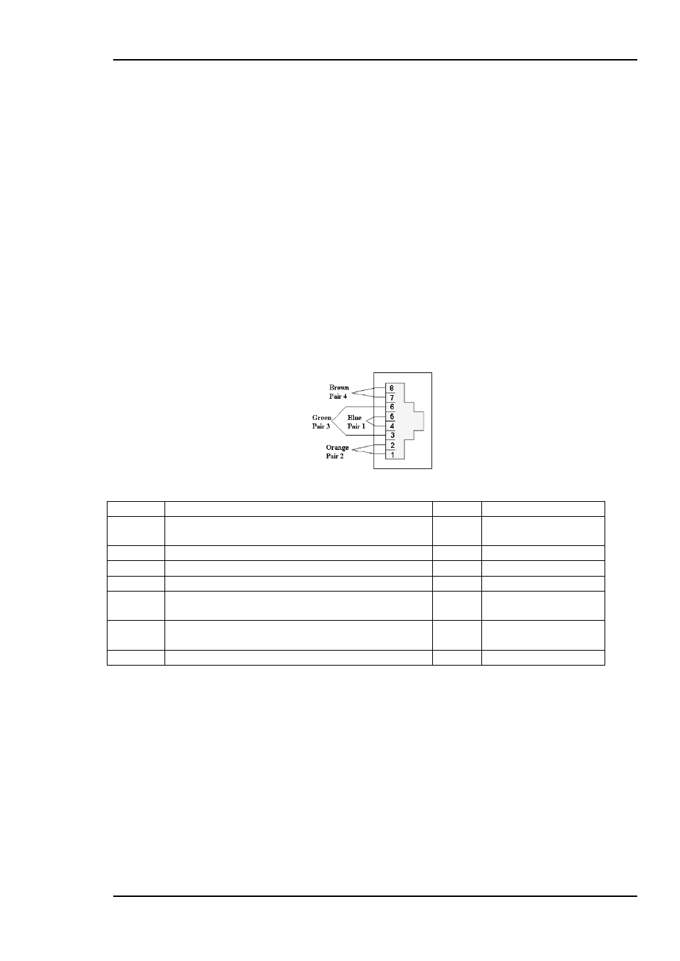
The GPI connector is shown in figure below.
LB-OE module GPI pinning:
Figure 4: GPI output.
Signal
Name
Pin #
Mode
Status
General error status for the module
(open = alarm)
Pin 1
Open Collector
LOS
Loss of Signal (open = signal detected)
Pin 2
Open Collector
LEVEL
Input level too high
Pin 3
Open Collector
H/L
Band select (open = low band = no tone)
Pin 4
Open Collector
H/V
Polarity horizontal/vertical
(open = horizontal = high voltage)
Pin 5
Open collector
DATA
Data input
Pin 6
CMOS Input
(Threshold at 2.5V)
Ground
0 volt pin
Pin 8
0V.
Electrical Maximums for GPI outputs:
Max current: 100mA
Max voltage: 30V