Nevion AAV-HD-XMUX User Manual
Page 13
AAV-HD-XMUX(-T/R)/ AAV-SD-XMUX(-T/R)
Rev. G
nevion.com | 13
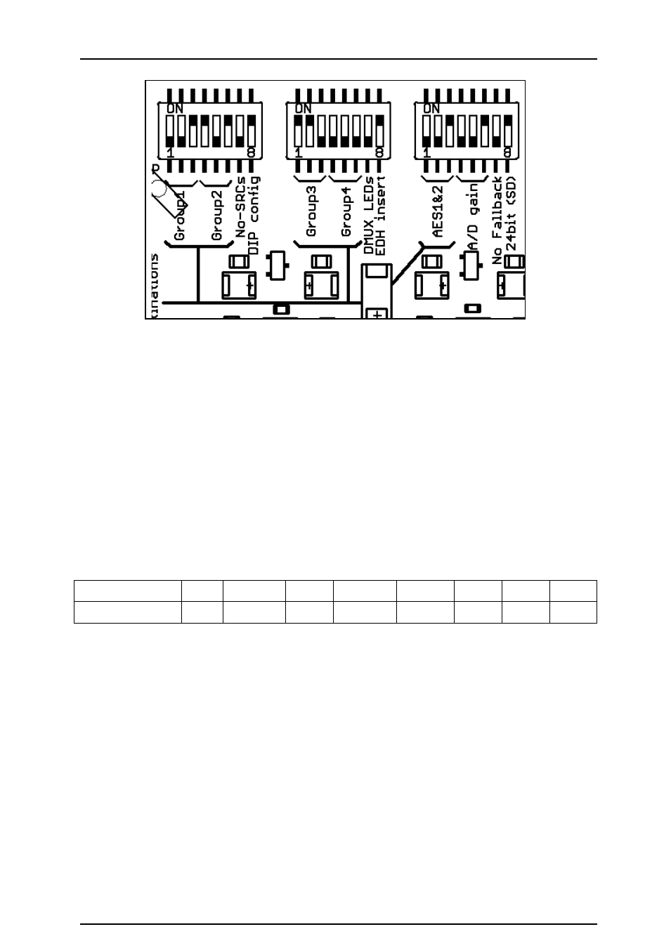
Figure 4: Example 2
The module above (Figure 4) is set to the following:
Group1 output is embedded with signals from de-embedded group1
Group2 output is embedded with signals from the ADC inputs
Group3 output is embedded with signals from AES1&2 inputs
Group4 output is not embedded
AES1&2 outputs signals from de-embedded group1
Users familiar with binary numbers may see that numbers 1 to 4 (001 to 100) correspond to
groups 1 to 4.
3.1.4 Other DIP Switches
3.1.4.1 A/D converter gain, SW3.4+5+6
The A/D input levels may be set to one of the eight preset levels. The levels correspond to
the maximum sine wave level, otherwise known as 0 dBFS.
SW3-4,5,6
000
001
010
011
100
101
110
111
Max.level (dBu)
+12
+13.5
+15
+16.7
+18
+20
+21
+24
All four input levels are set by the DIP switches in DIP configuration mode. GYDA can set the
levels for each stereo pair.
3.1.4.2 Non-SRC mode, SW1.7
When SW1.7 and SW1.8 are on, the sample rate converters will not be used. The user must
ensure that the AES input signals are locked to the video signal audio; otherwise click noises
will be produced in the embedded audio signals.
3.1.4.3 DIP Configuration, SW1.8
SW1.8 on, forces the DIP switch configuration to be used. If there is a GYDA present, the
switch configuration on the module will be used but the configuration will be monitored in the
GYDA controller. Control of the card parameters can not be changed with GYDA.
SW1.8 off will not use the DIP switches but will be configured from either the stored
configuration in the module or from GYDA if there is GYDA present. The configuration will be
stored when a GYDA configuration command is used. Therefore if a GYDA is present, the
internal configuration will be overwritten by the GYDA controller.