NIStune Type 1 Real-time User Manual
NIStune For the car
© 2007, 2008 NIStune Developments
NIStune Type 1 Real-time Daughterboard Instructions
Warning! Static Sensitive Components
Be aware of static electricity when handling the daughterboard. Although it is very rare to cause immediate
damage to components it can result in failure later on. This is true for all electronic equipment to some extent.
Try to keep the board wrapped in antistatic bubblewrap or similar while transporting it and try to ground
yourself to the ECU before fitment. While handling the board try to minimise activities like sliding around on
synthetic materials (eg: car seats) or walking on carpet, which generate large amounts of static electricity.
Fitting
a. Remove top and bottom from ECU. Using a cotton bud and acetone (or similar solvent) remove the
conformal coating from around the ROM chip/s you need to remove. Remove solder from the ROM chip
pins (and 4 connector pads if applicable) using a solder sucker.
b. Solder in 28 pin socket and connector cable (to either processor or connector pads if available on ECU).
Wire Z31/R31 Z31
Late
J30 S13/HR31
A31 HR31
Early
1. (Marked) Pin 34 (R/W)
Pad 33
Pad D
Pad 1
Pad near 61
Pad 3
2.
Pin 24 (A14)
Pad 32
Pad C
Pad 2
...
Pad 1
3.
Pin 25 (A15)
Pad 31
Pad B
Pad 3
...
Pad 4
4.
Pin 37 (E)
Pad 30
Pad A
Pad 4
Pad near 9
Pad 2
See Type 1 hardware installation document for detailed connector pin installation location.
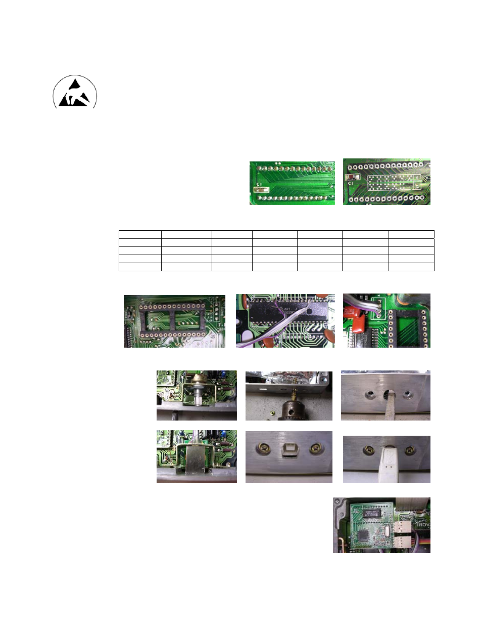
c. Remove diagnostics screw adjustment and enlarge diagnostic selector hole to fit USB connector
d. Insert the NIStune board into the socket and connect the CPU connector to X1 and USB connector to X2
e. To ensure the board does not come loose due to vibration, secure the board using a hot glue gun to the
edges of the ECU or other ECU components where available.
f.
Replace the ECU’s covers and you’re ready to go. All remapping is done via the USB Consult connector
using NIStune software.