NIStune Type 3 Daughterboard Fitting User Manual
NIStune For the car
© 2008 PLMS Developments
NIStune “Type 3” Daughterboard Fitting Instructions
Updated 24Jul08
Applicable vehicles:
S13/U13/RNN14 SR20DET
S14
(early)
SR20DET
N14
SR20DE
S13 KA24DE
Z32 (late) VG30DE(TT)
Be aware of static electricity when handling the daughterboard. Although it is very rare to cause immediate damage to
components it can result in failure later on. This is true for all electronic equipment to some extent. Try to keep the board
wrapped in antistatic bubblewrap or similar while transporting it and try to ground yourself to the ECU before fitment. While
handling the board try to minimise activities like sliding around on synthetic materials (eg: car seats) or walking on carpet,
which generate large amounts of static electricity.
Fitting
a. Remove top and bottom from ECU
b. Using a cotton bud and acetone (or similar solvent) remove the
conformal coating from both sides of the board where the 20+20
header will be fitted and from around the area of CJ1/CJ2 (or
J010/J011 in case of the S14/Z32).
c.
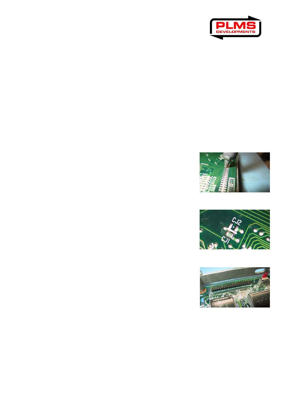
Remove solder from the 20+20 pads on motherboard where
daughterboard will be fitted.
d. On rear of motherboard remove link from “CJ1” and fit it to “CJ2” (in
case of S14/Z32 move J011 to J010). This will make the ECU
access the external maps (on the daughterboard) instead of using
its internal (factory) maps.
e. Solder the 20+20 way header to the motherboard. The
daughterboard now plugs directly onto this header. Make sure the
pins line up correctly with the holes in the socket or damage may
result. On S13 SR20 ECUs the board edge just touches the crystal
on one side.
f.
To ensure that the board does not come loose over time make sure you fit the self adhesive rubber strips.
Stick the strips (on top of each other to get the correct thickness) to the lid of the ECU above the
daughterboard. The daughterboard will then be pushed down firmly onto the rubber spacers when the lid
is fitted. It is important that the board is located correctly or problems with the connector may occur –
leading to intermittent operation.
g. Replace the ECU’s covers and you’re ready to go. All tuning is done via the Consult port using NIStune
software.
PLEASE REFER TO NISTUNE TYPE 3 HARDWARE INSTALLATION MANUAL FOR MORE DETAIL
FULL DOCUMENTATION AVAILABLE AT www.nistune.com