Configuration, Operation – Obvius A8911-23 User Manual
Page 6
5) Set the Modbus address dipswitches and baud rate dipswitch. For more information on the switch options, see the
section below for configuration.
6) Turn on the power supply. Confirm the green Alive LED starts blinking. Also check the RS485 yellow LEDs.
- If the A8911-23 receives any Modbus traffic on the RS485 port, the yellow RX led should blink.
- If the A8911-23 receives a Modbus query that is addressed to it specifically, the yellow TX LED should blink and
it will respond to the query.
If you are using an AcquiSuite Data Acquisition Server, the A9811-23 should appear in the Modbus device list after
about 2 minutes. Click on the device, and select “Configure” to give the A8911-23 a logical name. This will allow
the AcquiSuite to begin logging data for the device.
7) With the power disconnected, attach the pulse input lines to the pulse terminals. Each pulse input should have a
GND and a P# terminal. If the pulse output device is polarity sensitive, attach the pulse – terminal to the A8911-23
GND terminal, and the pulse + terminal to the A8911-23 P# terminal. The A8911-23 provides 3-5 volts on the P#
terminal for sensing. The remote pulse output device must not supply voltage to the terminals.
Wiring runs to pulse input terminals should be kept as short as possible. Wiring runs longer than 200 ft should be
avoided. Wiring should avoid proximity to sources of electrical noise such as running in parallel to electrical
cable, and VFD systems.
8) Power up the A8911-23. The Input LEDs for each connected input should now blink. The input LED will be on
when the contacts are closed.
WARNING: After wiring the A8911-23, remove all scraps of wire or foil shield from the electrical panel. This
could be dangerous if wire scraps come into contact with high voltage wires.
Configuration
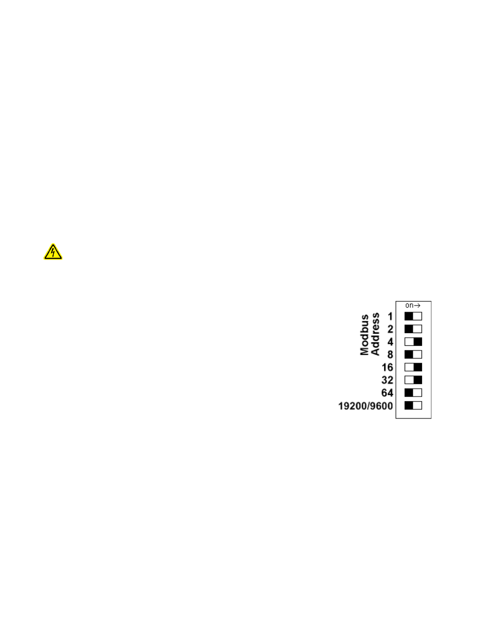
Modbus Address: Before the A8911-23 can be used, you must set the Modbus address of
the A8911-23. This address must be unique among all Modbus devices in the system. The
A8911-23 supports address 1 through 127.
Select an address, and set the dipswitches to match.
The sum of the value of the switches is the address. In the example to the right, address 52
is set by placing switch 4, 16 and 32 to the on position.
Note: 4 + 16 + 32 = 52
Baud Rate: This option sets the serial port speed for the RS485 port. Set this option to
“off” for 19200. Set the switch to “on” for 9600 baud.
Operation
The device should power up and be ready in a few seconds. The LEDs should blink in the following manner.
●
The green "Alive" LED should start to blink approximately once per second.
●
The yellow RS485 TX and RX LEDs will blink for local Modbus activity.
●
The red input status LEDs will blink when input contact closures are detected. Input status LEDs are adjacent to the
corresponding input screw terminals.
If the A8911-23 is attached to an AcquiSuite Data Acquisition Server, you will need to configure each pulse input with a
Name, Engineering Unit, and Multiplier.
Page 6
A8911-23