Nstallation – Olson Technology OTRR-3000 User Manual
Page 7
REV. X4
Page 7
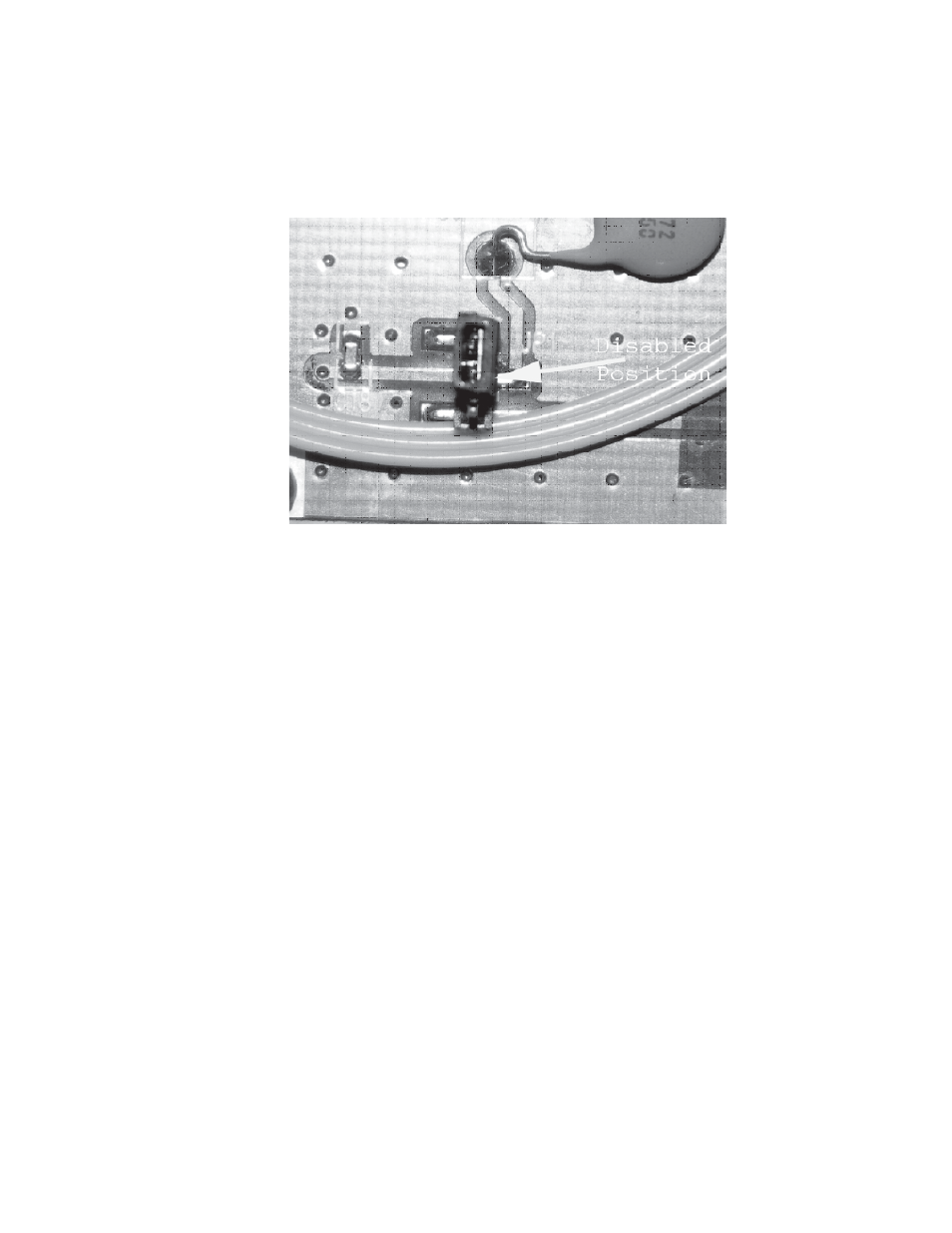
The Rx standalone unit can be powered though the RF connector, this feature can be enabled or disabled (Factory
Preset) by moving internal jumper, see picture below. The Rx unit is normally fed via the two flying leads, the Red Wire
is +8V
DC
to +24 V
DC
and the Black Wire is ground or -. The flying cable also has a shield wire that can be connected
to ground to help shield any external signals. The Brown (may also be White) Wire is an Open Collector Low Optical
Level Alarm that alarms when the optical level falls below -15 dBm.
Rx JUMPER JP1
Flying Lead Signal Description:
COLOR
Tx/Rx
SIGNAL DESCRIPTION
Red
Tx
DC Input, 8-24 V
DC
Black
Tx
Ground, DC Return
Silver
Tx
Shield, Shield wire, connect to Ground
Red
Rx
DC Input, 8-24 V
DC
Black
Rx
Ground, DC Return
Silver
Rx
Shield, Shield wire, connect to Ground
Brown
Rx
Open Collect Output for Low Received Optical Power
I
NSTALLATION
Optical Connectors
There are many optical connectors on the market. There are also different ways the optical cable is terminated such as
“Flat” and “Angled”. We use only use APC type of connectors Angled Precision encountered in the field is the use of
the wrong type of connectors. The most common is using SC/PC (Flat) with SC/APC(angled). The connectors will fit
together but the optical loss will be in the neighborhood of 10 dB.