Gbd-x wiring – Orion System GBD-X Controller User Manual
Page 6
FILENAME
DATE:
B. CREWS
DESCRIPTION:
PAGE
DRAWN BY:
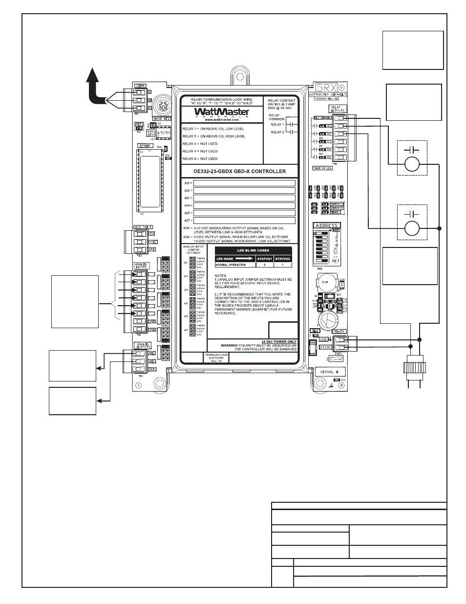
OE332-23- GBDX Controller
JOB NAME
OE332-23-GBDX-Wire1A.CDR
FILENAME
JOB NAME
Note:
All Relay Contacts
Are N.O. & Rated
For 1 Amps
@ 24VAC
Maximum
R1
R2
1 of 5
GBD-X Wiring
4.) All Wiring To Be In Accordance
With Local And National Electrical
Codes And Specifications.
3.) Set-up, Programming And
Monitoring Of The GBD-X
Controller Requires The Use Of A
Personal Computer And Prism
Software.
24VAC
GND
OE33 -2 -
GBD
Device Wiring
When Used For CO Applications
2
3 GBDX
-X
2
Available Inputs
For Connection
of CO Sensor
4-20mA Signal
See Page 2 For
Detailed
2
CO
Sensor Wiring
2
Connect The GBD-X
To The Same Local
Communications Loop
As The Controller
That Will Be
Receiving the GBD-X
Broadcast
Communications Wire
Must Be 2 Conductor
Twisted Pair With
Shield, Belden #82760
Or Equivalent.
All Wiring Must Be
Straight Through,
R To R, T To T And
SHLD To SHLD.
Available Relay #1
24 VAC Output
Closes On Rise
Above Minimum
CO Setpoint
2
24 VAC Pilot Duty
Relay (By Others)
24 VAC Pilot Duty
Relay (By Others)
Available Relay #2
24 VAC Output
Closes On Rise
Above Maximum
CO Setpoint
2
Available
0-10 VDC
Proportional
Output Signal
Available
10 VDC Fixed
Output Signal
Line Voltage
24 VAC Transformer
8 VA Minimum
2.) 24 VAC Must Be Connected
So That All Ground Wires
Remain Common.
Notes:
1.) The GBD-X Can Either Be Used
With CO2 Sensors Or Space
Temperature Sensors But Not
Both On The Same GBD-X
Controller. Up to 2 GBD
Controllers Can Be Located On
Each Local Loop.
AI1
AI1
SET
AI2
SET
AI3
SET
AI4
SET
AI5
SET
AI7
SET
AI2
AI3
AI4
AI5
AI7
10/21/10