Controller overview, Features, Operation – Orion System MHGRV III User Manual
Page 3: Figure 1: mhgrv iii controller dimensions, The mhgrv iii provides the following, Reheat enable command, Philips, 1 uf
Operator Interface
3
MHGRV III Controller Technical Guide
General
The MHGRV III Controller is designed to control a Modulating Hot
Gas Reheat Valve to maintain a desired Supply Air Temperature and
Humidifi cation setpoint. The controller can be used as a stand-alone con-
troller or it can be connected to and used in conjunction with the AAON
Factory Packaged HVAC unit controller. The MHGRV III controller is
connected to the HVAC unit controller via a modular expansion cable
and corresponding connectors on the controllers.
Features
The MHGRV III provides the following:
Can be operated as a stand-alone controller or
integrated with the HVAC Unit Controller
Provides for Supply Air Temperature Setpoint
reset when required
Second stage reheat capability when using
2 Hot Gas Reheat Valves
Control of reheat solenoid valve to provide coil
fl ushing for positive refrigerant oil return
Expansion capabilities for controlling additional
modulating hotgas values
Operation
When used in a stand-alone application (not connected to an HVAC unit
controller board), the MHGRV III controller will control the Modulating
Controller Overview
Hot Gas Valve to maintain the Supply Air Setpoint based on the Supply
Air Temperature Sensor connected to the MHGRV III controller. The
MHGRV III controller is activated by a 24 VAC wet contact closure
signal connected to the H1 (RHT EN) input terminal on the controller.
Heating Override and Cooling Override are also controlled by 24 VAC
wet contact closure signals connected to the HEAT OVR and COOL
OVR input terminals on the controller. The Supply Air Setpoint is set
by confi guring a DIP switch on the MHGRV III controller board. Sup-
ply Air Temperature Reset is also available and is set by confi guring
a DIP switch on the controller board. When Supply Air Temperature
Reset is used, it is reset by a 0-10 VDC signal supplied to the RESET
IN terminal on the MHGRV III controller.
When the MHGRV III controller is connected to an HVAC unit control-
ler board via its modular cable, it will operate exactly as the stand-alone
controller except that the following information will be passed between
the MHGRV III controller and the HVAC unit controller:
Reheat Enable command
Supply Air Temperature Setpoint. This replaces the
setpoint that is set with the Supply Air Temperature DIP
switch on the MHGRV III controller.
The Reset Supply Air Temperature Setpoint. This replaces
the setpoint that is set with the Supply Air Temperature
Reset DIP switch on the MHGRV III controller. The Supply
Air Temperature Reset Signal is also supplied from the
HVAC unit controller.
If the communication is interrupted between the MHGRV
III controller and the HVAC unit controller, the
MHGRV III controller will revert to stand-alone operation.
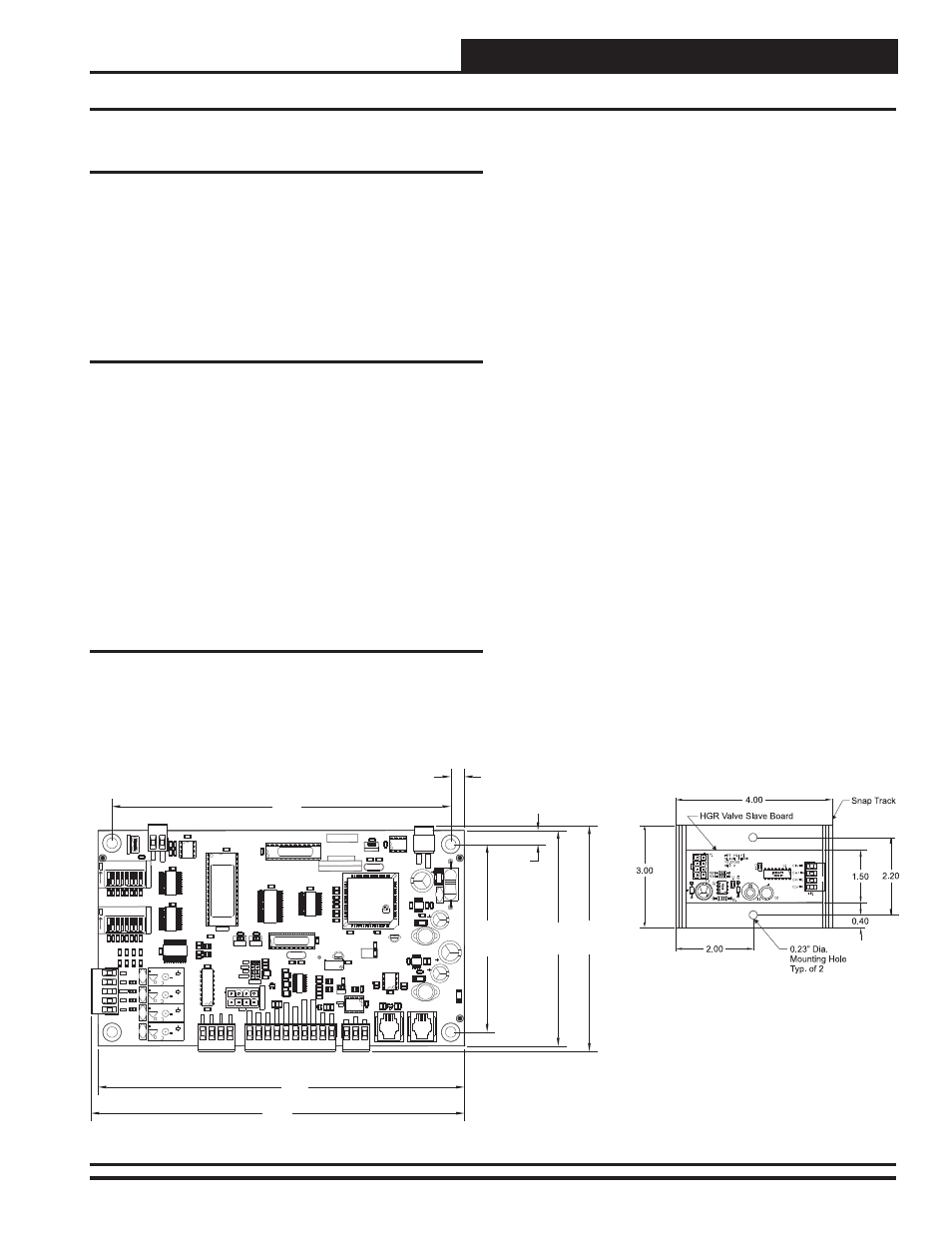
Figure 1: MHGRV III Controller Dimensions
128
64
32
16
8
4
2
1
SERIAL#
1 2 4 8 16 32 64 128
WATTMASTER
CONTROLS
WDOG
C29
U16
C22
R61
U20
U12
U11
R77
R76
R75
R74
C1
3
C36
X2
VR1
V5
V4
V3
V2
V1
U19
U18
U17
U15
U14
U10
U9
U8
U7
U6
U4
U2
TB
6
TB
5
TB4
TB3
TB2
TB1
SW2
SW1
R7
3
R7
2
R7
1
R7
0
R6
9
R6
6
R6
5
R6
4
R63
R62
R60
R59
R58
R5
7
R5
6
R5
5
R5
4
R53
R5
2
R5
1
R5
0
R4
9
R4
8
R4
7
R4
6
R4
5
R4
4
R4
3
R4
2
R4
1
R4
0
R3
9
R3
5
R3
4
R3
3
R3
2
R3
1
R3
0
R2
9
R2
8
R2
1
R2
0
R1
9
R1
8
R1
7
R16
R15
R1
4
R1
3
R11
R1
0
R9
R8
R7
R6
R5
R4
R3
R2
R1
P2
P1
L2
L1
K4
K3
K2
K1
J2
D1
7
D1
5
D12
D11
D8
D7
D5
D3
D2
D1
C35
C34
C3
3
C31
C30
C28
C27
C26
C25
C24
C2
3
C21
C2
0
C18
C1
4
C12
C11
C10
C9
C8
C7
C6
C5
C4
C3
C2
C1
C16
P4
R78
U13
C15
C17
C19
R22
R23
R24
R25
R26
R27
R36
R37
R38
U22
U23
D10
U21
U1
R79
C
OOL
OVR
GND
SAT
H
EAT
OVR
RH
T
E
N
R
ESE
T
IN
AU
X
IN
GND
GND
+VDC
SH
R
T
V
AVL
E
EXP
STAT
STEP
0-5V
0-10V
4-20
THERM
FAN
CMP
VALV
E
AUX
COM
CG
/H
R
CR
/H
G
CW
/H
W
CB
/H
B
AUXIN
R
E
S
E
T
LIM
IT
S
E
TP
O
IN
T
AD
D
A
D
D
24
VAC
GND
REC
POWER
YS102138REV
3
HOTGAS
REHEAT
III
AO
U
T
GND
C
H
AS
SI
S
G
ND
EPROM
485
DRV
OFF
OFF
PHILIPS
PCB80C552-5-16WP
500650=1/3
DFD9940SM
PHILIPS
10A250VAC
~
5A30VDC
SA
VDE
G5Q-1A4
OMRON
DC24V
CHINA
10A250VAC
~
5A30VDC
SA
VDE
G5Q-1A4
OMRON
DC24V
CHINA
10A250VAC
~
5A30VDC
SA
VDE
G5Q-1A4
OMRON
DC24V
CHINA
10A250VAC
~
5A30VDC
SA
VDE
G5Q-1A4
OMRON
DC24V
CHINA
.1
uF
74
HC541
TPIC6B259
74
HC541
.1uF
.1uF
.01uF
.1uF
.1uF
.1uF
.1uF
.1uF
10uF
10uF
22pF
22pF
10uF
10uF
10uF
10uF
.1uF
.1
uF
.1
uF
10
uF
.1
uF
.1
uF
10uF
1002
1002
1002
1002
1002
1002
1002
1002
1002
1002
1002
1002
1002
1002
10
02
10
02
10
02
10
02
10
02
10
02
10
02
1002
1002
10
02
10
01
10
01
10
02
22
11
LM358
4751
1002
3650
3650
04
04
.1uF
1002
1002
1002
4751
4751
4751
1002
1002
1002
LT1785
04
04
22pF
22pF
75
00
10
10
75
00
04
10
02
10
02
36
50
47
51
P82B96
.1
uF
4751
4751
3650
.1uF
.1uF
100pF
100pF
1002
1002
15
02
17
41
38
31
1211
.2
2
.2
2
NE
50
90
L2
93
D
N
E
34063
34063
1N5819
1N5819
93C46
74
HC573
CY62256LL
2500
3001
3011
RS
1G
10
02
0
P
S
2815-
4
4751
4751
4751
3001
3001
22
11
22
11
22
11
22
11
22
11
22
11
22
11
SF000093a
11.059Mhz
11.059Mhz
WARNING
OBSERVE
POLARITY
SF000140
D16
U5
VREF
D13
D14
R1
2
4.70
0.30
4.92
4.10
8.00
7.40
0.30
8.15