E-bus digital room sensor, Connecting a remote sensor, Operator interface 14 – Orion System E-BUS Digital Room v.1 User Manual
Page 14: Figure 20: attaching a remote sensor, 2u f, Oe231 return air temperature sensor
E-BUS DIGITAL ROOM SENSOR
Operator Interface
14
Connecting a Remote Sensor
Connecting a Remote Sensor
NOTE: The following directions are for the OE217-02 Space
Temperature Only E-BUS Digital Room Sensor. If you
are using an OE217-03 or OE217-04 Space Temperature
and Humidity Model, please contact WattMaster Techni-
cal Support for instructions.
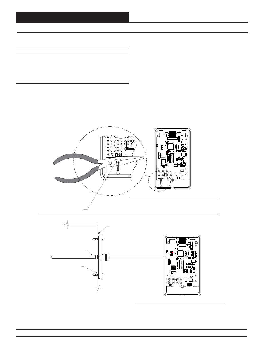
Sometimes due to the requirements of a job, the temperature sen-
sor must be located outside the conditioned space due to special
requirements such as hospital surgical room codes, security, or
tampering considerations. In these cases, the E-BUS Digital Room
Sensor can be mounted in a different room and have a remote tem-
perature sensor connected to it. Typically, this would be a Return
Figure 20: Attaching a Remote Sensor
OE217-02 E-BUS Digital Room Sensor Back View
OE217-02 E-BUS Digital Room Sensor Back View
Sensor Shown With
Back Cover Removed
Sensor Shown With
Back Cover Removed
Cut Wire Loop As Shown.
Make Sure That The Wires
Are Cut Close Enough To
The Circuit Board So They
Can’t Touch Each Other.
Mount Sensor In Return Air
Duct As Shown. Route Wires
To Digital Room Sensor
Location And Connect To
Terminal Block.
Return
Air Duct
OE231 Return Air
Temperature Sensor
MADE IN USA
YS102370 R1
ModBus LCD Space Sensor
WattMaster Controls, Inc
PROGRAM
CO
M
M
LED
1
EXTERN
THERM
+12Vdc
GND
-COM
+COMM
SHLD
P1
R1
F3
U4
C18
R3
6
C3
0
D1
L1
C1
7
R38
R3
7
C1
9
C31
C21
TB1
X2
J3
C3
C2
4
C23
C1
C8
C1
2
C1
3
C1
4
C16
C25
C2
6
J2
Q2
R3
R4
R6
R8
R9
R10
R11
R12
R14
R13
R15
TH1
U3
X1
C27
R18
C20
D4
R17
D6
D7
R3
2
R3
3
D5
1
J1
DISP1
C1
5
D2
R2
R5
R7
R16
R19
R20
U6
U2
TB2
R35
2
.2uF
R18
1002
1001
1330
4751
4751
1001
1001
.1uF
9.
2
1
M
h
z
4751
4751
LT
C
3
5
0
2
.1uF
15
p
F
6.
8
u
F
.1
u
F
10uF
3162
1502
6.8uH
1002
24F
C1
0
2
5
6.8uF
6.8uF
1001
4751
.1uF
.1
u
F
1000
1002
4751
.1uF
4751
ADM
34
83
.1
u
F
.1
u
F
RS1G
X0
5
M
ICRO
C
H
IP
PI
C3
2
M
X4
4
0
F
512H
-80
IP
T
.1
u
F
10RO
10RO
470pF
X0
5
MADE IN USA
YS102370 R1
ModBus LCD Space Sensor
WattMaster Controls, Inc
PROGRAM
CO
M
M
LED
1
EXTERN
THERM
+12Vdc
GND
-COM
+COMM
SHLD
P1
R1
F3
U4
C18
R3
6
C3
0
D1
L1
C1
7
R38
R3
7
C1
9
C31
C21
TB1
X2
J3
C3
C2
4
C23
C1
C8
C1
2
C1
3
C1
4
C16
C25
C2
6
J2
Q2
R3
R4
R6
R8
R9
R10
R11
R12
R14
R13
R15
TH1
U3
X1
C27
R18
C20
D4
R17
D6
D7
R3
2
R3
3
D5
1
J1
DISP1
C1
5
D2
R2
R5
R7
R16
R19
R20
U6
U2
TB2
R35
2.
2
u
F
R18
1002
1001
1330
4751
4751
1001
1001
.1uF
9.
2
1
M
h
z
4751
4751
LT
C
3
5
0
2
.1uF
15
p
F
6.
8
u
F
.1
u
F
10uF
3162
1502
6.8uH
1002
24F
C1
0
2
5
6.8uF
6.8uF
1001
4751
.1uF
.1
u
F
1000
1002
4751
.1uF
4751
ADM
34
83
.1
u
F
.1
u
F
RS1G
X0
5
M
ICRO
C
H
IP
PI
C3
2
M
X4
4
0
F
512H
-80
IP
T
.1
u
F
10RO
10RO
470pF
X0
5
Air Duct Temperature Sensor. Usually, you will be using the OE231
Return Air Temperature Sensor, but you can also use any Type III
10K Ohm Thermistor Sensor.
To connect a remote temperature sensor to the Digital Room Sensor, you
must fi rst remove the E-BUS Digital Sensor’s back cover. You will see
a loop of wire hanging off of the sensor circuit board. See Figure 20.
This is the sensor’s temperature sensing element (thermistor). Clip the
thermistor loop wire so that the sensor will read the remote temperature
input. Be sure to cut the ends of the wire close to the circuit board so that
the sensor loop wire ends won’t short between each other. The remote
sensor then wires to the remote sensor terminal block on the back of
the E-BUS Digital Room Sensor. If using the WattMaster OE210 type
Space Sensor as the remote sensor, you must clip off the yellow C1
capacitor from the back of the OE210. Be sure to cycle power to begin
reading the remote sensor.
Revised 05/01/12