Research Concepts RC2000C User Manual
Page 23
RC2000C Az/El Tracking Antenna Controller
Chapter 3
Installation/Setup
15
Research Concepts, Inc. • 5420 Martindale Road • Shawnee, Kansas • 66218-9680 • USA
www.researchconcepts.com
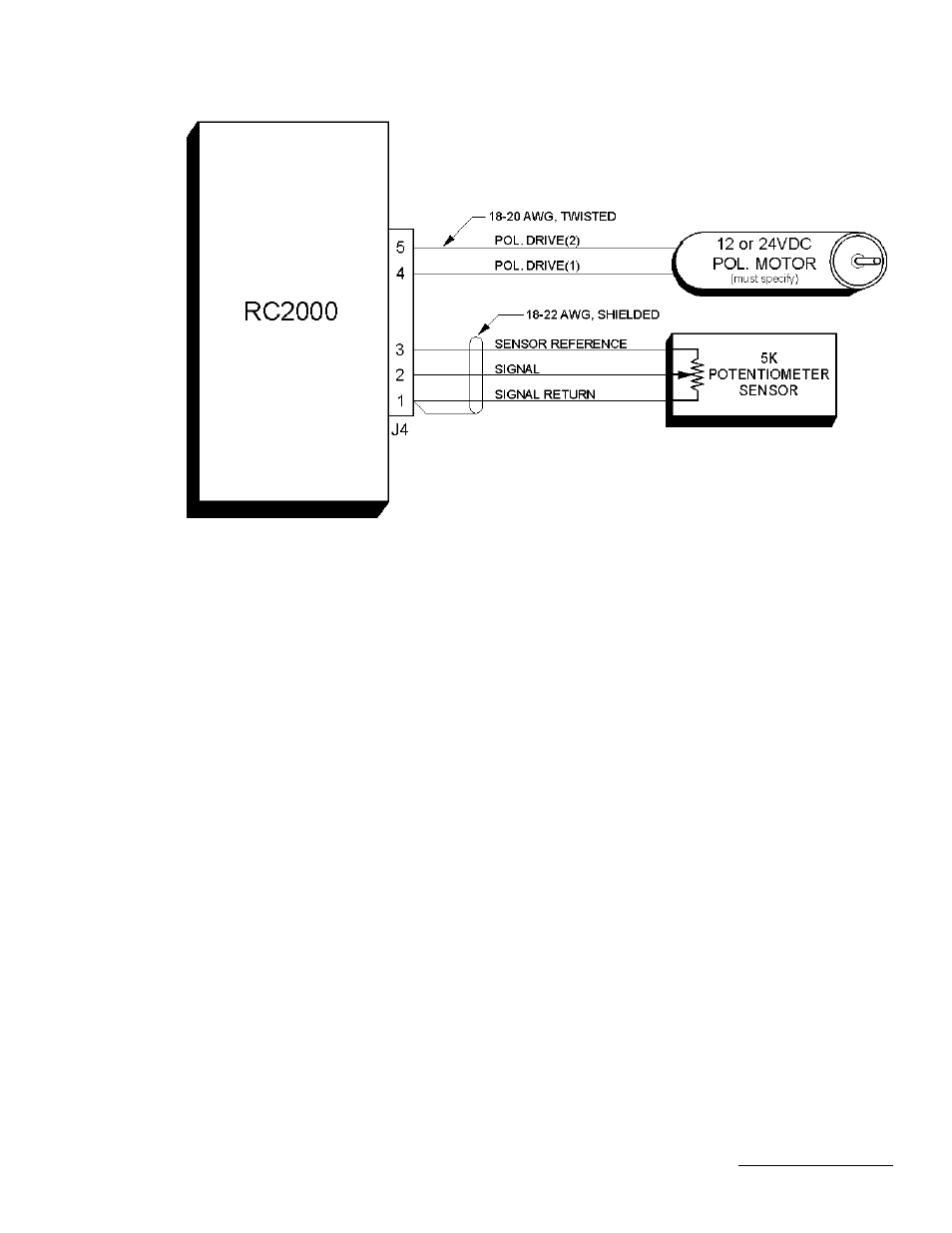
Figure 3.4 - RC2KPOL Option
5. Tighten the allen screw and verify that the pot is properly centered by performing the procedure
above entitled "Verifying Pot Center Position".
Use the following procedure to configure the RC2000C for use with a 24V DC polarization motor.
1. Connect the polarization/sensor assembly as shown in figure 3.4. Note that shielded cable is
recommended for the sensor connection. If a shielded cable is used the shield MUST be
connected to the GROUND terminal (1) of connector J4 at the back of the controller and MUST
NOT be connected to anything at the antenna. At the potentiometer use heat shrunk tubing to
prevent foil shielding material from coming in contact with earth ground at the antenna
2. The CONFIG mode Rotating Feed Present item must be set to YES (1). Activate CONFIG mode
and use the SCROLL DOWN key to bring up the Rotating Feed Present item and key in a 1
followed by the ENTER key. (If the Rotating Feed Present item is not accessible in CONFIG mode;
the Expert Access flag has been reset. If this occurs, perform a system reset as described in
section 3.1.)
3. In this step the polarity of the polarization motor and sensor wiring is checked. The motor polarity is
somewhat arbitrary. The polarization jog keys are labeled POL CW and POL CCW. The user is
free to define the direction sense as they wish. To change direction of motor rotation associated
with CW and CCW, swap the motor drive wires attached to connector J4 terminals 4 and 5
(DRIVE). The important thing is that when the polarization motor is jogged CCW, the position count
MUST INCREASE. If this is not the case, the wires attached to the connector J4 terminals labeled
3 (REF) and 1 (RTN) must be reversed. Note that the shield must always be connected to the RTN
terminal.
To check the polarity of the polarization motor, the rotating feed limits must be set so that
unrestricted movement of the feed is possible. To achieve this, the Rotating Feed CW Limit
CONFIG mode item must be set to 0, and the Rotating Feed CCW Limit CONFIG mode item must
be set to 1023.
The polarization motor may be jogged in MANUAL mode. Jog the pol motor and make sure that
movement is in the proper direction - position count increasing for CCW movement. Note that once
the rotating feed limits have been configured as described above, there are no limits on polarization