Step 11-power, Step 1 set output resolution, Step 4-scale – RGBLink VSP 729 Quick start User Manual
Page 2: Step-usb port, Step 3- input switch, Step 8-lan (ethernet) port, Powering up, Step 5-save
Step 11-Power
Plug in power cord which has IEC connector, VSP 729
support AC power from 85 to 260 VAC,50-60Hz, which
means world wide compatible.VSP 729 supports dual
power backup.
Step 1
Set Output resolution
Push OUT button and use UP or DOWN button to go
to right resolution for the monitor or display system,
and push SEL button to decide to go to the resolution.
VSP 729 supports the following resolution:
800x600x60Hz 1024×768×60Hz
1280×768×60Hz 1600x1200x60 1920x1080x60
NOTE
Step 2
Programming input signal
Step 10-Serial port
Local Control
Front Panel Control
VSP 729 supports 8 Composite input, 4 VGA input
(YPBPR), 4 DVI input( HDMI 1.3) ,Background 4x
DVI (DVI 1.0), connect the input to the
corresponding connector.
NOTE
Step 4-Scale
NOTE
Step-USB Port
Connect control PC to USB port via USB cable.
VSP 729 supports 4 channels programming
User can programme and select the signals through
1234 preview buttons and PRO button in the front
panel, and preview the signal through preview output
in the rear panel. All the programming is finished in
preview channel, Background signal is not
programmable.
NOTE
Step 3- Input Switch
NOTE
Step 8-LAN (Ethernet) port
Use twist CAT5 cable to connect to LAN port, user can
control VSP 729 based on default IP address:
192.168.0.100. User can also change the IP address by
RS 232 or USB.
Twist CAT5 should be one end in T568A, and another
end in T568B standard.
LAN(Ethernet) port is not for standard configuration.
Pin
End 1
Wire Color
End 2
Wire color
1
White-green
White-Orange
2
Green
Orange
3
White-Orange
White-green
4
Blue
Blue
5
WhiteBlue
White-blue
6
Orange
Green
7
White-Orange
White-brown
8
Orange
Brown
Crossover Cable
CAT5 is
wired as
T568A at
one end and
T568B at the
other(Tx and
Rx pairs
reversed) is
crossover.
T568A
T568B
Pins
Use RS232 to RJ11 cable to connect a control system
or computer to the back panel RJ11 port and the other
end on RS232 port. RS232 to RJ11 cable as following
definition.
RS-232
Funtion
2
TX
Transmit
3
RX
Receive
5
GND
Signal Ground
7
---
Not used
8
---
Not used
Pin
RS-422
Funtion
TX-
Transmit(-)
RX-
Receive(-)
GND
Signal Ground
RX+
Receive(+)
TX+
Transmit(+)
Insert Twisted
Pair Wires
RS232/RS422
Connector
Insert Twisted
Pair Wires
RJ11
Connector
RJ-11
Funtion
1
TX
Transmit
2
RX
Receive
3
GND
Signal Ground
4
---
Not used
Pin
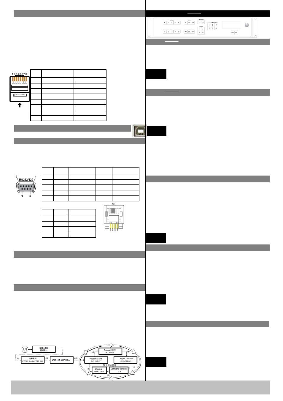
Powering Up
Push power button switcher to ON position. LCD
module on the front panel will show RGBLINK and
VSP 729 model information, and go into self verification
before it load the last setting configuration data and send
the processed image to the target displayor device. User
can operate with VSP 729 through local front panel and
remote control with the software run on the PC, remote
control by RS232, USB or TCP/IP.
VSP 729 Quick Start
Rev 1.0
Page 2 of 3
Address:S603-604 Weiye Building Torch Hi-Tech Industrial Development Zone Xiamen,Fujian Province, P.R.C
Tel: 00865925771197 Fax:00865925771202
Email: [email protected] http://www.rgblink.com
There are two different switch ways:
CUT and TAKE:
CUT is the direct switch without transiting effect
TAKE has the transiting effect, for example there are
WIPE and FADE. In WIPE menu there are many
modes to choose. And in FADE menu duration of
Fade-in-Fade-out can be set.
Current mode can be figured out according
to the light of WIPE or FADE button.
Push Scale button and go into scale setting menu. Use
UP or DOWN to go to Horizontal size, Vertical size,
Horizontal position, Vertical position setting page, and
push SEL to decide to set, and use UP or DOWN to
change the size or position value. Push SEL to send and
exit from the setting.
Keep pushing UP or DOWN button, the value
of the size or position will change faster and
Faster during setting values.
Rate of change will be from 1 to 10 and to 100.
Step 5-Save
VSP 729 support 3 user saving modes. Push SAVE
button and SVAE1, SVAE2, SAVE3 buttons will light
on, push any one of them to save the setting. After that
user can push each of them to call the setting.
SAVE1 setting is default user setting after
VSP 729 power on.
All the user settings will gone after factory reset.