SoundTraxx LC Series Owners Manual User Manual
Page 10
LC SERIES DIGITAL SOUND DECODER OWNER’S MANUAL
10
backup light and special effect lights. The outputs
can be independently programmed for a multitude
of Hyperlight effects and may be used in a variety
of ways. See page 25 for more information. Each
output is rated for 100mA.
Do not exceed this rating! Be sure that the
combined current of all lights as well as the
motor stall current measured in Step 2 does
not exceed the decoder’s current rating.
The DSD-LC lighting outputs may be used with
12-16 volt incandescent lamps or 1.5-volt micro-
bulbs. The DSD-LC is
not designed for use with
LEDs as they may glow faintly even when the function is turned off.
Other Considerations
Finally, you will need to
decide whether or not to
hardwire the electrical
connections or use a
plug-able connector. A
connector will allow you
to easily separate the
components for storage,
painting and service
easier but also opens
the possibility of ac-
cidentally damaging the
decoder by reversing the connector during reassembly. Hardwiring the decoder will prevent this
possibility at the expense of making separation more difficult.
After you have fully read the installation instructions that came with your decoder, we suggest
you draw yourself a schematic showing all connections between the DSD-LC and various sub-
components. This will help you determine which type of connector is best suited for your needs.
Step 4. Isolate the Motor
The two motor brush connections must be electrically isolated so they are driven
exclusively by
the DSD-LC motor outputs. We’re not kidding about this!
Failure to properly isolate the motor will damage your decoder and turn it into an
effective, but short-lived smoke generator!
In the event you do damage your decoder, simply return it to SoundTraxx along with the service
fee (please call for current amount) and we will repair and return it promptly. See our Service
and Warranty Policy, page 36.
Begin motor isolation by removing the body shell from the locomotive and in the case of a steam
locomotive, the tender shell as well.
Before you proceed further, it is important to carefully examine the locomotive wiring and deter-
mine where each wire goes and what it does. The manufacturer’s assembly drawings may be
useful here or you may elect to create your own wiring diagram. In particular, you will need to
identify the connections to the left and right power pickups as well as the (+) and (-) motor con-
nections. Note: for N, HO, and S scale locos, the positive motor connection is the one connected
to the right rail (engineer side) power pickup.
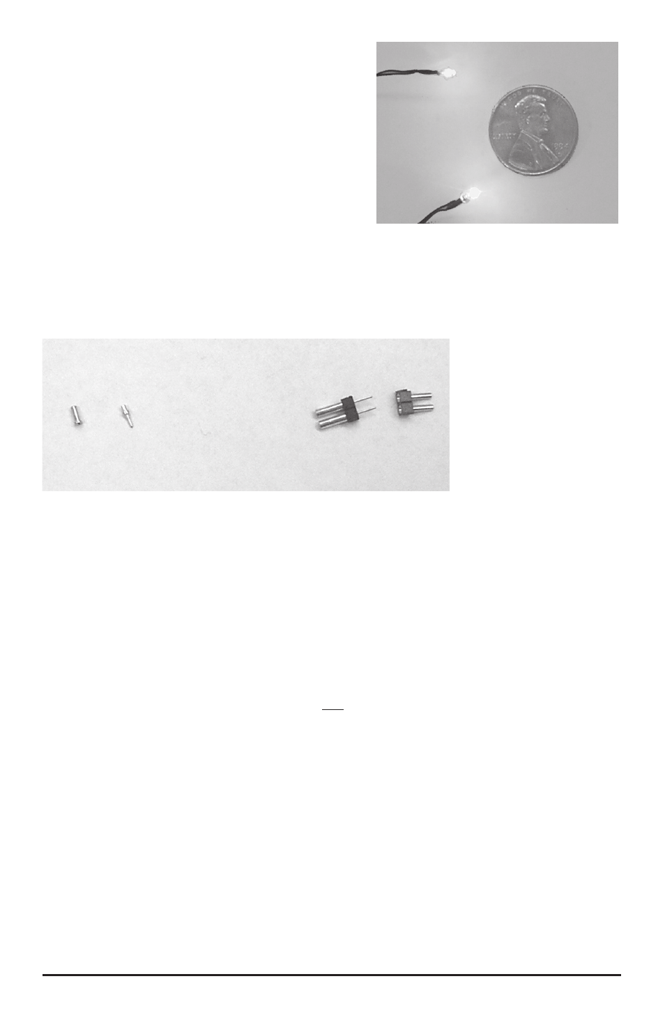
1.3mm
Microbulbs
2.5mm
Microbulbs
Figure 6 - Microbulbs for use with
Hyperlight effects
Figure 7 - Mini-connectors can make installation easier