Sundance SMT339 v.1.3 User Manual
Page 15
Version 1.2
Page 15 of 27
SMT339 User Manual V1.3
CLK_DIR
– When ‘0’ the Video Port 0 clk0 and clk1 pins are both driven by the
decoders pixel clock. When ‘1’ the Virtex pins are tri-stated.
CTRL_DIR
– Driving of the various Video 0 control signals.
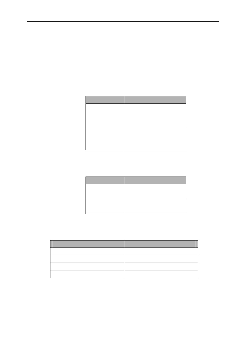
The tables below shows the state of video port control and data signals for different
values of CTRL_DIR and CLK_DIR.
CTRL_DIR
‘0’
(this mode used
for embedded
sync input)
Vp0_ctrl0 - ‘1’
Vp0_ctrl1 - ‘1’
Vp0_ctrl2 - ‘Z’
‘1’
Vp0_ctrl0 - Dec Hsync
Vp0_ctrl1 - Dec Vsync
Vp0_ctrl2 - Dec ODD
Table 8 : Video Port 0 and Decoder connectivity
CLK_DIR
‘0’ Vp0_clk0
-
dec_pclk
Vp0_clk1 - pclk
‘1’ Vp0_clk0
-
‘Z’
Vp0_clk1 - ‘Z’
Table 9 : Video Port 0 and Decoder Clock connectivity
Video Port 0 Data Pins
Video Decoder Data Pins
VP0_D(19..12)
Decoder_C(7 .. 0)
VP0_D(11..10) ‘00’
VP0_D(9..2)
Decoder_Y(7 .. 0)
VP0_D(1..0) ‘00’
Table 10 : Video Port 0 Decoder Data to Video Port Data Mapping