Tim connectors’ position – Sundance SMT358 User Manual
Page 22
Advertising
Version 2.5
Page 22 of 25
SMT358 User Manual
Figure 9 shows the Physical Layout of the SMT358, indicating the external
connectors with their location and numbering.
Connector definitions are as follows:
SDB
A,B,C,D
: Digital Data & Clock Input /Output Signal – Sundance Digital Bus High
Density ODU connector A (40-way High Density IDC Connectors).
JTAG
: JTAG Signals – 6-way connector.
P1 :
Top
Primary
connector.
P2
: Bottom Connector. (Bottom Primary and Global Expansion Connectors)
Table 2: SMT358 connector reference table
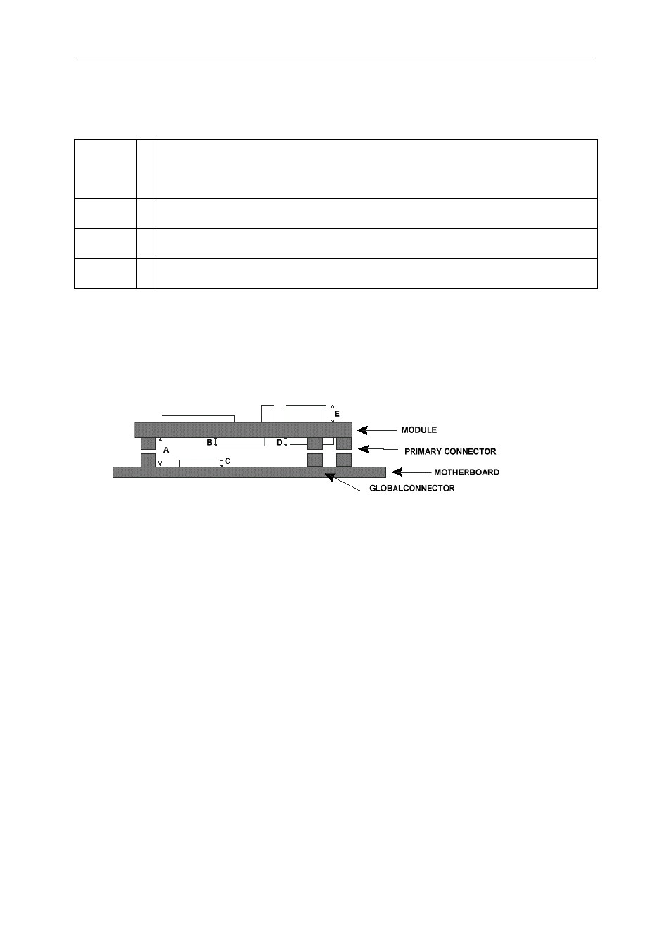
TIM Connectors’ Position
Figure 10: Tim Connectors’ position
Advertising