Sundance SMT8090-395 User Manual
Page 9
Advertising
Version 1.2
Page 9 of 12
SMT8090 User Manual
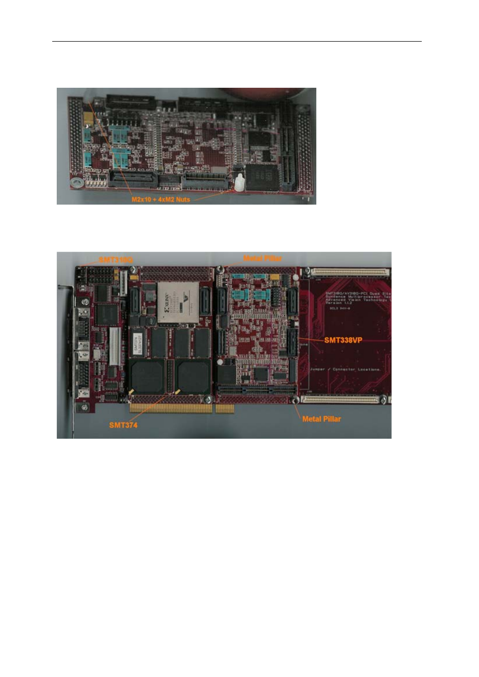
b – Then fit four M2 nuts on each screw.
c – Place the SMT338 on the second site (SMT395 already on first site) on the
SMT310Q and fit two metal pillars (3.3 Volts).
d – Place the SMT390 on top of the SMT338-VP. Make sure that both
modules fit firmly.
e – Fit two M2 nuts on the Nylon screws and two M3x4 screws in the 3.3V pillars.
3 – Connect CommPort 0 of the SMT395 to CommPort 3 of the SMT390 (T1C0 to
T2C3) via an FMS cable at the back of the SMT310Q.
4 – Connect SHBA on the SMT395 to SHBA on the SMT390-VP via the SMT516.
5 – Connect SHBB on the SMT395 to SHBB on the SMT390-VP via the SMT511
(SHB to SHB cable).
Advertising