Sundance SMT911 User Manual
Page 10
SMT911 User Manual SMT911
Page 10 of 38
Last Edited: 01/06/2010 10:09:00
• 4 SMA connectors (50 Ohm) for dual-band antennas providing TX/RX
• Two MMCX connectors (50 Ohm) external clock input
• Samtec BKT connector for 5 V and 3.3 V power supply
• 120-pin Samtec QSH connector for all digital I/O signals
• JTAG connector for debug/access to FPGA on base-board.
• Plugs directly into a wide range Sundance SLB TIMs
Each pin on the BKT power connector (33 pins in total) can carry 1.5 A. Digital 5V
(D+5V0), digital 3V3 (D+3V3) and digital ground (DGND) are provided over this
connector. D+3V3 and D+5V0 are assigned four pins each. The daughter card can
thus draw a total of 6A of each of these two supplies.
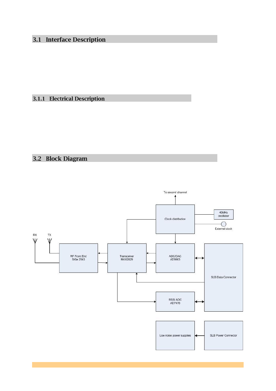
The major elements of the SMT911 are shown in the block diagram below (single
channel shown).