Clock register e 0x1e, Clock register f 0x1f – Sundance SMT943 User Manual
Page 29
User Manual SMT943
Page 29 of 54
Last Edited: 23/08/2011 17:24:00
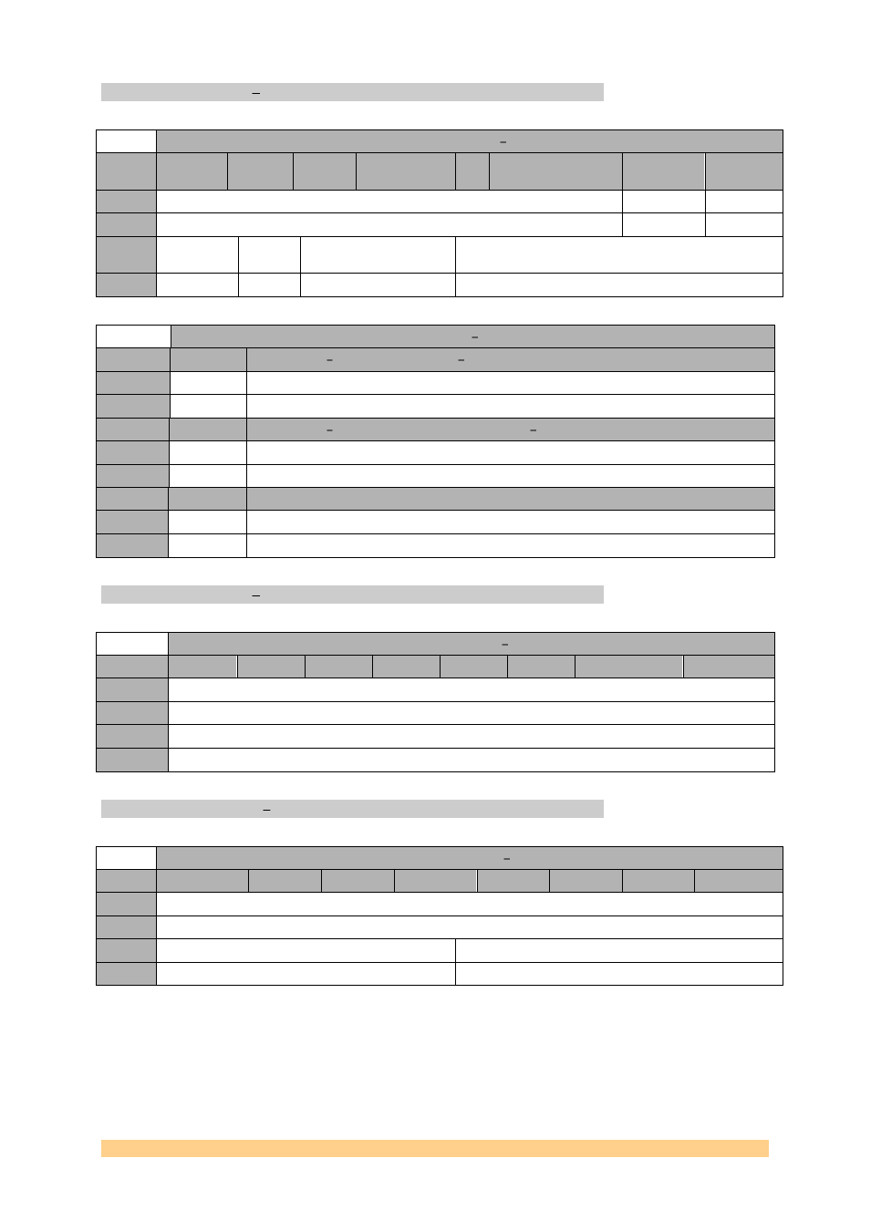
CLOCK Register E 0x1E.
Clock Register E 0x1E
Byte
Bit 7
Bit 6
Bit 5
Bit 4
Bit
3
Bit 2
Bit 1
Bit 0
1
Reserved
ADLOCK
LOCK_C[1]
Default
‘000000’
‘0’
‘0’
0
LOCK_C[0]
Reserve
d
LOCK_WINDOW
Reserved
Default
‘0’
‘0’
‘00’
‘0111’
Reset Register E 0x1E
Setting
Bit 5:4
Description Lock detect window LOCK_WINDOW
0
‘0’
1
‘1’
Setting
Bit 8:7
Description Number of coherent lock events LOCK_C
0
‘0’
1
‘1’
Setting
Bit 9
Description ADLOCK
0
‘0’
Digital PLL Lock
1
‘1’
Analog PLL Lock
CLOCK Register F 0x1F.
Clock Register F 0x1F
Byte
Bit 7
Bit 6
Bit 5
Bit 4
Bit 3
Bit 2
Bit 1
Bit 0
1
Reserved
Default
‘01101000’
0
Reserved
Default
‘00000000’
CLOCK Register 10 0x20.
Clock Register 10 0x20
Byte
Bit 7
Bit 6
Bit 5
Bit 4
Bit 3
Bit 2
Bit 1
Bit 0
1
Reserved
Default
‘00000001’
0
Reserved
Reserved
Default
‘0111’
‘1000’