3electrical connections – Super Systems X5 User Manual
Page 10
Advertising
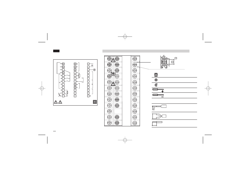
Terminals
6
5
4
3
2
1
28
27
30
29
26
25
7
19
31
8
20
32
9
33
10
34
11
23
35
12
24
36
0,5
Nm
16
15
18
17
14
13
21
Rear
terminal
cover
Cable size
1 mm
2
[2]
5.7 mm
0.22 in
10
3 - Electrical Connections
3
ELECTRICAL
CONNECTIONS
C
N
L
1
2
3
4
5
6
7
8
9
10
11
12
19
20
23
24
25
26
27
28
29
30
31
32
33
34
35
36
TC
mV/V/mA
NC
C
NO
OP3
NO
C
NO
OP1
OP2
OP4
DG
OP6
(option)
24V—
OUT
1
2
3
A
b
B
RTD
13
14
15
16
17
18
21
22 N/C
LOGIC
INPUT
Pr
ofibus
VP
DP
DN
OP5
IN1
C
RS485 (Slave)
POT
0%
REM
NO
C
3.1 TERMINAL BLOCK [1]
B
35 screw terminals M3
Option terminals
Holding screw 0.5 Nm
Phillips screwdriver PH1
Flat blade screwdriver
0.8 x 4 mm
Pin connector
q 1.4 mm - 0.055 in max.
Ø
Fork-shape AMP 165004
Ø 5.5 mm - 0.21 in
L
Stripped wire
L 5.5 mm - 0.21 in
UL notes
[1] Use 60/70 °C copper (Cu) conductor only.
[2] Wire size 1 mm
2
(18 AWG Solid/Stranded)
X5-SSI-uk 18-03-2009 17:53 Pagina 10
Advertising