Setup instructions – TE Technology MP-2986 User Manual
Page 4
4
Setup Instructions
1.
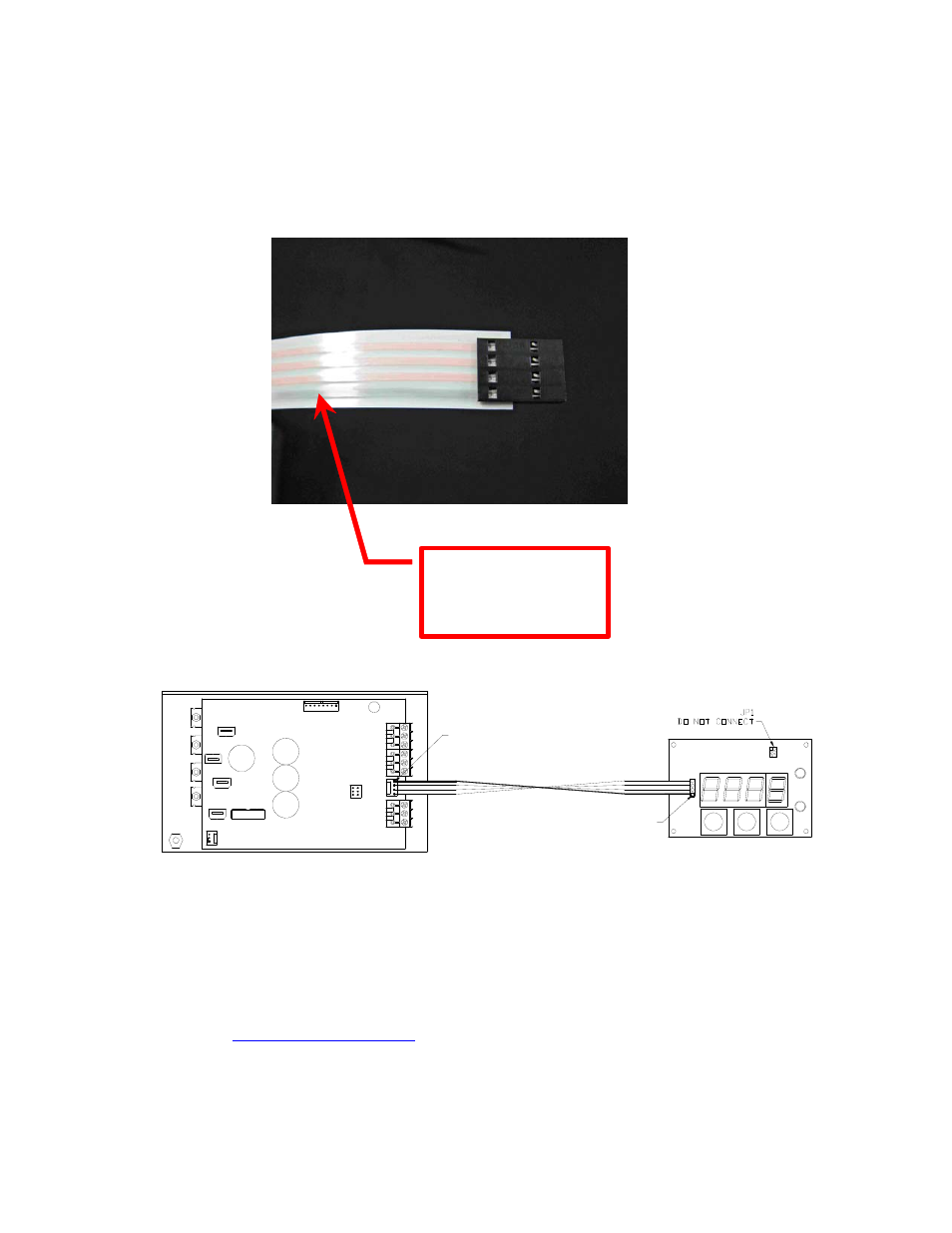
Make sure the controller is not powered. Connect the flat-flex cable to JP2 on the MP-2986
and JP3 on the TC-36-25 RS232. Make sure the gray-shaded conductor connects to Pin 1
on JP2 and Pin 1 on JP3.
Note: the connection diagram above shows only the connection between the MP-2986 and
the TC-36-25 RS232. Other connections to the controller are not shown for the sake of
clarity.
The cable length provided is 457 mm (18 in.). You can use a longer flat-flex cable though if
necessary. However, the maximum allowable length is 910 mm. Longer cables can be purchased
from Digi Key (
http://www.digikey.com
). The basic part number is A9BBG-F-ND. The
first two boxes correspond to the number of connectors; the next two boxes correspond to the
length of the cable, in inches. For example, suppose you want a length of 610 mm. This is
equivalent to 24 inches, so the part number would be A9BBG-0424F-ND. Digi Key only lists
standard parts of up to 8 inches (203.2 mm) length, so you will need to contact them to verify
availability.
gray-shaded conductor
must connect to Pin 1
of JP2 on display and
JP3 on controller
JP6
WP1
WP3
WP2
WP4
JP3
PIN 1
JP2
PIN 1