31] shift, 5 rear panel, 32] digital (aes/ebu) input/output – Teac DA-40 User Manual
Page 16: 33] digital (coaxial) input/output, 34] control i/o, 35] remote in, 36] power cord, 37] (balanced) analog inputs, 38] (unbalanced) analog inputs, 39] (unbalanced) analog outputs
2 - Parts of the tape deck
16
TASCAM DA-40
[31] SHIFT
This key is a latching key. When active, the indicator
beside and above the key lights, and the command
keys take on their shifted functions, as indicated by
the blue captions above them.
See 4, "SHIFT functions" for details of these shifted
functions.
2.5 Rear panel
[32] DIGITAL (AES/EBU) INPUT/OUTPUT
These XLR-type connectors conform to the AES/
EBU3-1992 standard and are used to accept
(
INPUT
) and transmit (
OUTPUT
) digital audio data
in that format. The
INPUT
connector can also
receive balanced IEC60958 format (SPDIF) data.
The format of data received (AES/EBU or SPDIF) is
automatically detected.
[33] DIGITAL (COAXIAL) INPUT/OUTPUT
These RCA connectors conform to the IEC60958
standard (SPDIF), and are used to accept (
INPUT
)
and transmit (
OUTPUT
) digital audio data in that
standard. The
INPUT
connector can also receive
unbalanced AES/EBU3-1992 format data. The for-
mat of data received (AES/EBU or SPDIF) is auto-
matically detected.
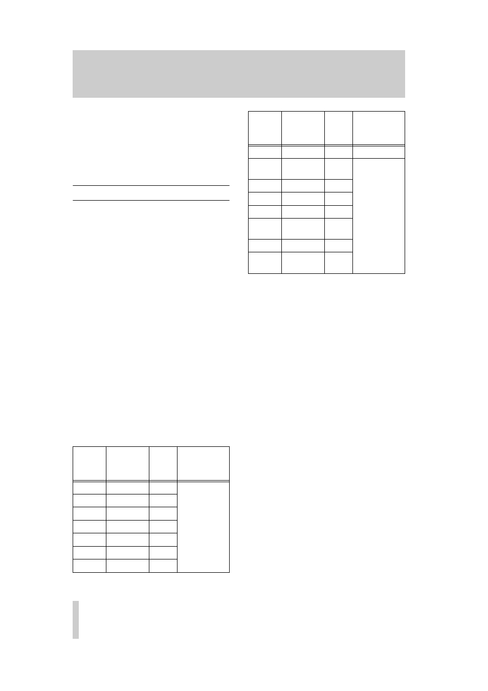
[34] CONTROL I/O
This 15-pin ’D’-sub connector is used for connection
to a suitably-equipped controller.
As well as the mode described in the table below, this
connector can also be used as a serial connector.
Please contact your TASCAM distributor for details
of this facility.
The pinouts of this connector are given below:
[35] REMOTE IN
This 3.5 mm jack is used to connect the optional RC-
D45 remote control unit.
Do not use this jack to connect any remote control
unit other than one designed especially for use with
the tape deck.
[36] Power cord
Make sure that the power supply voltage matches the
voltage requirements of the tape deck as marked on
the rear panel. If there is any doubt, consult your
TASCAM dealer.
[37] (BALANCED) ANALOG INPUTS
These female XLR connectors provide balanced
inputs at a nominal +4 dBu level. The wiring of these
connectors is:1 = ground, 2 = hot, 3 = cold. The nom-
inal impedance of these connectors is greater than
25 k
Ω
.
[38] (UNBALANCED) ANALOG INPUTS
These RCA connectors provide unbalanced inputs at
a nominal –10 dBV level. The nominal impedance of
these connectors is greater than 50 k
Ω
.
[39] (UNBALANCED) ANALOG OUTPUTS
These RCA connectors provide unbalanced outputs
at a nominal –10 dBV level. The nominal impedance
of these connectors is less than 1 k
Ω
.
Pin
number
Signal
Direction
Function
1
STOP
IN
External com-
mand reception;
active when low
(at ground poten-
tial for 30 ms or
more)
2
FWD PLAY
IN
3
F.FWD
IN
4
REW
IN
5
PAUSE
IN
6
REC PLAY
IN
7
SERIAL
IN
8
Ground
—
—
9
FWD PLAY
TALLY
OUT
Transmit trans-
port status indica-
tion signals in
open collector
(maximum allow-
able voltage 15 V
and maximum
allowable current
80 mA)
10
F.FWD TALLY
OUT
11
REW TALLY
OUT
12
STOP TALLY
OUT
13
REC/PLAY
TALLY
OUT
14
PAUSE TALLY
OUT
15
TAPE END
TALLY
a
OUT
a. See 3.10, "End tally signal"
Pin
number
Signal
Direction
Function