Working principle – Tecfluid COVOL Series User Manual
Page 4
4
1 WORKING
PRINCIPLE
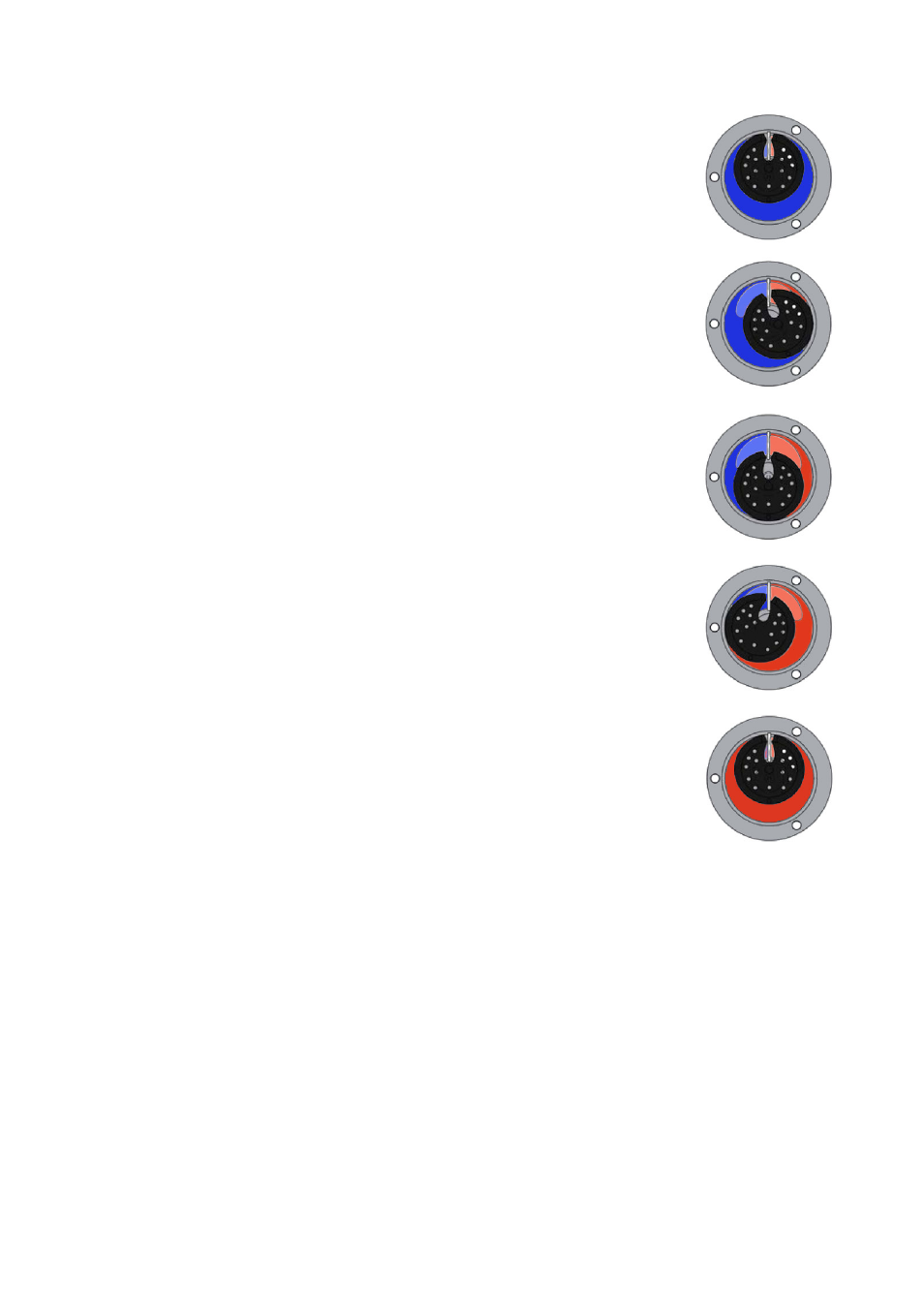
By means of oscillating piston and an annular measuring
chamber.
1– The first figure shows the COVOL flowmeter at the beginning
of a cycle, when the measuring chamber (in blue) is
completely full.
2– The flow of the liquid through the flowmeter makes a force on
the oscillating piston, so that it starts turning. From this moment
the measuring chamber is divided in two parts: inlet (in red) and
outlet (in blue).
3– The liquid fills progressively the inlet measuring chamber (in
red), as it is getting emptied on the outlet (in blue). In the middle
of the cycle (see figure) the two chambers are the same size.
4– At this stage the outlet measuring chamber has already
emptied almost all the liquid corresponding to a cycle, while on
the inlet it is almost filled with the liquid corresponding to the next
cycle.
5- At the end of the cycle, the inlet measuring chamber takes all
the space. From this moment it can be considered that this is
already the outlet chamber, so we are again at the beginning of
the cycle.
As one can see, a constant volume of liquid is moved in each
cycle.
The piston includes a magnet inside that activates a reed switch
each complete turn. The output signal can be treated by means of
an electronic converter.