7 electrical connection – Tecfluid COVOL Series User Manual
Page 7
7
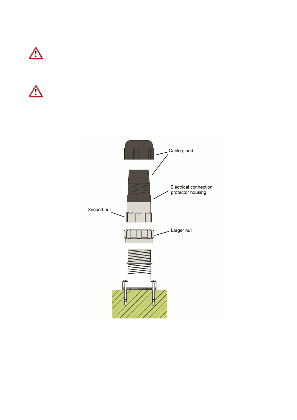
Loosening the larger nut in the middle of the connector allows us to withdraw the half
where the cable will be later soldered.
The other half of the connector is fixed to the counter and should not be removed, except
when servicing the detector (See point 4.3 of the MAINTENANCE section).
The removable part of the connector consists of the cable gland at the top and the
electrical connection protector housing.
This way the presence of air pockets in the flowmeter is avoided, which could cause false
readings. In particular, the associated electronics would show a volume higher than real.
Note: In order to avoid cavitations, the API Std 2534 standard must be taken into
account. This standard states that on the outlet of the flowmeter the pressure must be at
least twice the pressure drop of the flowmeter (in case of COVOL, this pressure drop is
3 mH2O or 0.3 bar, for fluids with viscosity 1 mPa·s at maximum flow rate), plus 1.25
times the vapour pressure of the liquid or its most volatile components.
3.7 Electrical
connection
It is important to keep the connecting cable between the flowmeter and the associated
electronics away from mains or power supply cables, in order to avoid interferences. In
any case, those should be separated at least 5 cm.
The COVOL oscillating piston flowmeter has a connector fastened to the counter by
means of 4 screws. The connector consists of 3 parts joined by threaded nuts. (See
figure).