Upsite 10161 Modular Containment: Rack Top Vertical Baffle User Manual
Rack top baffle assembly instructions, Installation guide, Installation instructions
Rack Top Baffle Assembly Instructions
Covers Part Numbers:
10160 and 10161
Installation Guide
The 2-pak carton contains
components to assemble
(2) AisleLok
®
Rack Top Baffles includes:
(2) Clear Plastic Panel Assemblies
(4) Magnet Tails Assemblies
(2) Adjustment Clips
SAFETY REQUIREMENTS
The AisleLok
®
Rack Top Baffle Assembly attaches to the tops of IT rack cabinets using strong rare earth magnets. Use extreme
caution when handling the powerful magnets. Make sure to keep fingers clear of the contact area between the magnets and
the metal mounting surface.
For proper mounting, the AisleLok
®
Rack Top Baffle magnets must make direct contact with a steel or other ferrous metal
surface, e.g. rack top panel, rack frame, etc. Any obstruction that prevents the magnets from making direct metal contact will
reduce the holding force of the magnets and may cause the AisleLok
®
Rack Top Baffle to fall. Installation will likely require the
use of a ladder or moveable stairs, caution should be exercised when climbing up and down ladders/stairs. When standing on
the ladder/stairs, be careful of overhead lighting or cabling.
Installation Instructions:
AisleLok
®
Rack Top Baffle Assembly
1. Determine the best attachment position for the Magnet Tails
The tail assembly can be mounted in a number of different
positions. The outer most positions often work best on many
cabinets. Before attaching the tails to the extrusion base, make
sure to inspect the top surface of the cabinet the AisleLok
®
Rack
Top Baffle Assembly will be mounted to. Many cabinets have cable
cutouts, or other potential interference issues that must be avoided.
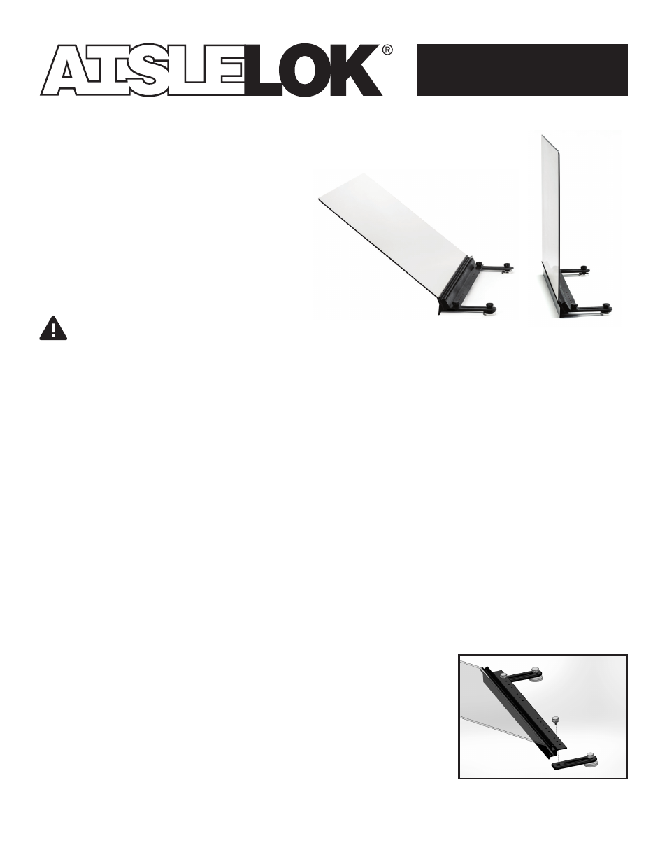
2. Attach the Tail Assemblies to the Extrusion
The magnet comes preassembled to the magnet tail with a
thumbscrew. The magnet position is adjustable on the tail,
but movement of the magnet is rarely needed.
a. With the most optimum mounting location identified, remove
the thumbscrew from the tail assembly, which is NOT attached
to the magnet.
b. Position the tail assembly beneath the desired hole on the
extrusion base flange. Insert the thumb screw thru the required
hole on the extrusion base and thread into the receiving
threaded hole on the tail assembly. Tighten by hand. Repeat for
the 2nd tail assembly.