Verilink 1024 Chassis (CG) Configuration/Installation Guide User Manual
1024 chassis, Configuration guide, Verilink 1024 chassis front view
1024 Chassis
Configuration Guide
45-00123
3.0
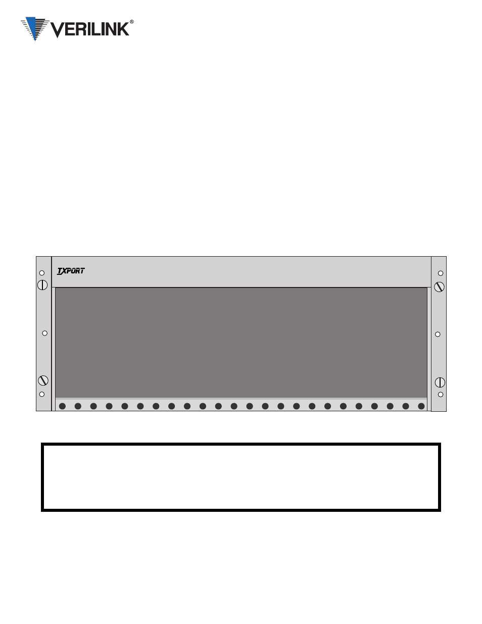
Verilink 1024 Chassis Front View
The Verilink 1024 chassis is designed to hold from
one to twenty-four modules.
The front view figure shows the chassis with brack-
ets for a 19-inch rack. The rear panel NMS and pow-
er connections are described on the reverse side.
Each module interfaces the chassis backplane board
through two card connectors. With these connectors,
each module receives a
−
48 VDC power source and
exchanges control signals with the rear panel chassis
connectors. The chassis contains no active compo-
nents.
Rack mounting brackets are reversible for standard
19- and 23-inch racks. To install the chassis in a
rack, insert two screws through both the left and the
right mounting brackets. Please note: In order to
meet GR-1089 grounding requirements, the chassis
must be installed using thread-forming screws with
external tooth lock washers.
Specifications
Dimensions:
17.2" W, 7" H, 10.5" D,
Weight: 9.5
pounds
Operating Temp:
0° to 50° C (32° to 122°F)
Storage Temp:
−
20° to 85° C (
−
4° to 185°F)
Humidity:
95% max (non- condensing)
Caution: The 3002 is designed for convec-
tion cooling. Mount the 1024 with a top and
bottom clearance of at least 1¾ inches.
Industry Listings
FCC Compliance: Part 15 Class A
Subpart B
U.S. Safety:
UL 1950 3rd Edition
Canadian Safety:
CSA C22.2 No. 950-95
24
23
22
21
20
19
18
17
16
15
14
13
12
11
10
9
8
7
6
5
4
3
2
1
1024
CHASSIS
T
R
A
N
S
P
O
R
T
NOTICE: If your Verilink 1024 Chassis has a top assembly number of F-1024-000--120,
metal dividers are installed in slots 5, 10, 15 and 20. Removal of these dividers
voids NEBS compliance!