Nms connections, Power connections, Verilink 1024 chassis rear view – Verilink 1024 Chassis (CG) Configuration/Installation Guide User Manual
Page 2
TB1
OUTPUT
INPUT
+ 4 8 V D C I N A
C H A S S I S G N D
- 4 8 V D C I N A
- 4 8 V D C I N B
S I G N A L G N D
+ 4 8 V D C I N B
1
2
3
4
5
6
7
8
9
10
11
12
13
14
15
16
17
18
19
20
21
22
23
24
TB1
OUTPUT
INPUT
+ 4 8 V D C I N A
C H A S S I S G N D
- 4 8 V D C I N A
- 4 8 V D C I N B
S I G N A L G N D
+ 4 8 V D C I N B
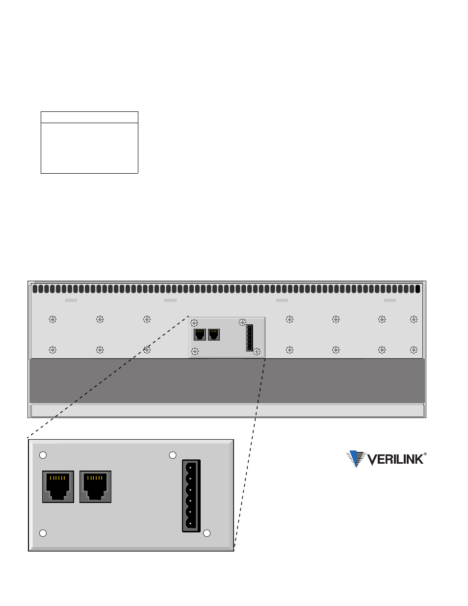
NMS Connections
The NMS ports are used to connect the chassis into
the Verilink EM8100A element manager. Within
the chassis, each unit is physically connected to the
next unit in a daisy-chain fashion. Two 6 - pin mod-
ular connectors are provided for both the A side
and the B side.
Each unit in the NMS chain must have a unique ad-
dress. All units in the chain must use the same
NMS bit rate.
Power Connections
The chassis is designed with two power buses con-
nected to TB1 (terminal block 1). The A bus feeds
the slots 1 through 12. The B bus feeds slots 13
through 24. Connect a Frame Ground lead (18- to
20 - gauge wire) to pin 2 before applying power to
the unit. Connect the other end of this lead to an ap-
propriate frame ground.
NOTE: The maximum current draw of a
fully loaded chassis is 4 amperes. The
Verilink 1042 power shelf can supply a max-
imum of 4 amperes (refer to the configura-
tion guide for specifications). Ensure that
the proper fuse size is used.
Pin
NMS In (P5) NMS Out (P4)
1
Not Used
Not Used
2
Signal Gnd
Signal Gnd
3
Data Out
Data Out
4
Data In
Not Used
5
Signal Gnd
Signal Gnd
6
Not Used
Not Used
Verilink 1024 Chassis Rear View
145 Baytech Drive
San Jose, California 95134
127 Jetplex Circle
Madison, Alabama 35758
(800) 837- 4546
www.verilink.com
FAX-On-Demand
(800) 957-5465
Technical Assistance Center
(800) 285- 2755