Verilink 1051-2 Chassis (CG) Configuration/Installation Guide User Manual
Configuration guide, Specifications, Enet connection
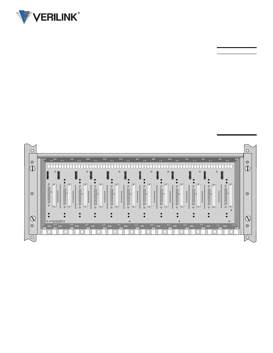
The Verilink 1051-2 chassis holds up to
twelve of the following modules:
2000 ESF CSU
3021 E1 NTU
2010 ESF CSU
4001 DDS CSU/DSU
2048 PMU/NTU
4010 DDS CSU/DSU
2100 CSU
4051 DDS CSU/DSU
3001 CSU/DSU
8100A Site Controller
Each module attaches to the chassis back-
plane board through two connectors. With
these connectors, each module receives
−
48
VDC power and exchanges control and input/
output signals. The chassis contains no active
components.
Specifications
Width:
17.2 inches (43.69 cm)
Height:
7 inches (17.78 cm)
Depth:
10.5 inches (26.67 cm)
Weight:
9.5 pounds (4.31 kg)
Opererating: 32° to 122°F (0° to 50°C)
Storage:
−
4° to 185°F (
−
20° to 85°C)
Humidity:
95% max (non- condensing)
Mounting:
Reversible ears for 19-inch or
23-inch racks
ENET Connection
The Ethernet
interface is a female
15-pin D-shell
connector with
slide latch located
on the lower right
rear corner of the
chassis.
Pin
Interface
3
Data Out (A)
10
Data Out (B)
11
Data Out (Shield)
5
Data In (A)
12
Data In (B)
4
Data In (Shield)
2
Control In (A)
9
Control In (B)
1
Control In (Shield)
6
Voltage Common
13
Voltage Plus
14
Voltage Shield
Shell Protectective Ground
Power Connections
The chassis is designed with two power buses
connected to TB2. The A bus feeds the odd
slots (1, 3, 5, 7, 9, and 11). The B bus feeds
the even slots (2, 4, 6, 8, 10, and 12). Connect
a Frame Ground lead (18- to 20-gauge) to
pin 2 before applying power to the unit. Con-
nect the other end of this lead to an appropri-
ate frame ground.
Redundant Power Source:
A power
board is factory installed on TB2 allowing the
connection of two independent
−
48 VDC
supplies operating in a redundant mode. All
slots are powered from the combined input of
the A and B power supplies. If one supply
fails, the other powers the entire chassis.
To operate in the redundant mode, connect
pins 3 and 4 (
−
48 V IN) on the redundant
power board to the negative (
−
) terminal of
the power supply. Connect pins 1 and 6 (+48
V RTN) to the positive (+) terminal of the
power supply.
Single Power Source:
When using a sin-
gle power source, connect the A bus termi-
nals (pins 4 and 6) on the redundant power
board to the corresponding terminals of the
power supply.
If the redundant power board is not used, the
A bus and B bus must be connected together
with a jumper (pin 3 to pin 4 and pin 1 to
pin 6).
Dual Power Source:
When using dual in-
dependent 48 VDC power supplies, one
source feeds the A bus while another source
feeds the B bus. First, remove the redundant
power board. Connect the A bus (pins 4 and
6) to the corresponding terminals of power
supply A (to power the odd numbered slots).
Connect the B bus (pins 1 and 3) to the corre-
sponding terminals of power supply B (to
power the even numbered slots).
The maximum current draw of a fully loaded
chassis is two amperes. The Verilink 1040
and 1041 power shelves can supply a maxi-
mum of two amps. Ensure that the proper fuse
size is used.
45-00050
3.0
1051- 2 Chassis
Configuration Guide