Txport 1051 rear view, Fuse – Verilink 1200 Rack Pwr Spply (IG) Configuration/Installation Guide User Manual
Page 2
T
R
A
N
S
P
O
R
T
®
1051 to 1200 Connections
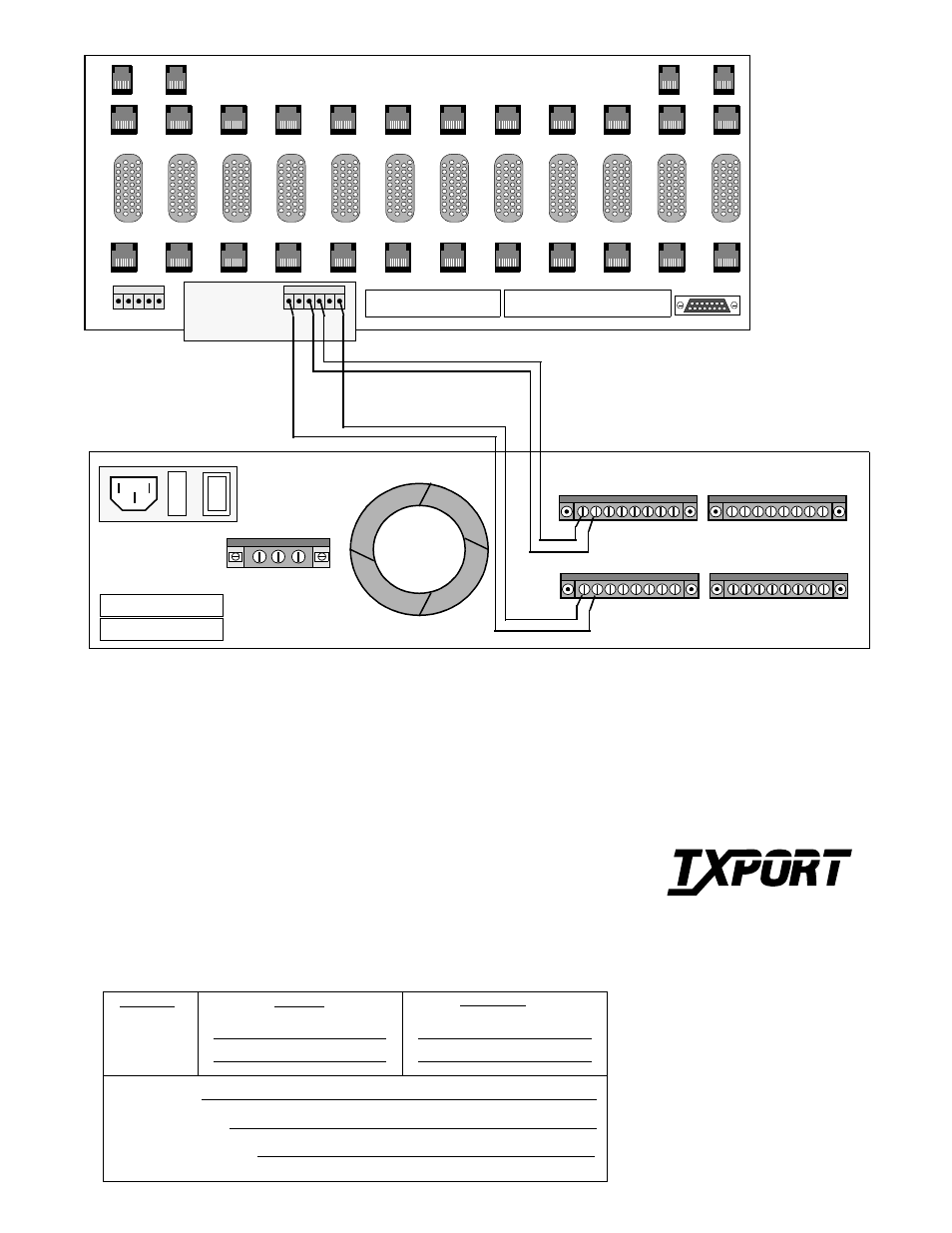
The TxPORT 1200 RMPS can support up to three 1051 shelves (redundant five amp configuration) or up to six shelves when configured for
non-redundant 10 amp operation. All wiring connections between the 1200 and the 1051 shelf should be made using 22-gauge stranded wire,
or larger. The maximum power requirements for a 1051 shelf are 1.65 amps, -48 VDC.
-48 VDC
9 10111213141516
-48 VDC
1 2 3 4 5 6 7 8
RTN
1 2 3 4 5 6 7 8
RTN
9 10111213141516
ALARM
COM NC NO
MODEL NO.
SERIAL NO.
I
O
FUSE
( A )
ENET
High
Speed
DTE
12
High
Speed
DTE
11
High
Speed
DTE
10
High
Speed
DTE
1
High
Speed
DTE
2
High
Speed
DTE
3
High
Speed
DTE
4
High
Speed
DTE
5
High
Speed
DTE
6
High
Speed
DTE
7
High
Speed
DTE
8
High
Speed
DTE
9
NMS
OUT
( A )
NMS
IN
( B )
NMS
IN
T1
DTE
12
T1
DTE
11
T1
DTE
10
T1
DTE
9
T1
DTE
8
T1
DTE
7
T1
DTE
6
T1
DTE
5
T1
DTE
4
T1
DTE
3
T1
DTE
2
T1
DTE
1
TB2
2 3 4 5 6
1
1 - EXT CLK
2 - EXT CLK
3 - ALARM RING
TB1
4 - ALARM TIP
5 - SIG GND
1 - +48V RTN (B)
2 - FRAME GND
3 - -48V IN (B)
4 - -48V IN (A)
5 - SIG GND
6 - + 48V RTN (A)
TB2
T1
NET
12
T1
NET
11
T1
NET
10
T1
NET
9
T1
NET
8
T1
NET
7
T1
NET
6
T1
NET
5
T1
NET
4
T1
NET
3
T1
NET
2
T1
NET
1
( B )
NMS
OUT
8
1
1
6
8
1
TB1 - 2 3 4 5
1
Redundant
Power
Board
RTN A
RTN B
-48 A
-48 B
Primary
Phone:
Date installed:
Secondary
Name:
Contacts:
Date last serviced:
Location:
TxPORT 1200 RMPS Rear View
TxPORT Customer Service
127 Jetplex Circle
Madison, Alabama 35758
Customer Service Returns:
800-926-0085, ext. 227
Product Technical Support
(8 a.m. to 5 p.m.)
800 -285-2755 or
205-772-3770, ext. 255
After Hours Hot Line:
205-551-7538
To connect a 1051 shelf to the 1200, attach one end of a stranded wire to TB2 terminal 4 labeled
-48 V IN (A) on the 1051 shelf. Attach the opposite end of the stranded wire to any one of the 16
terminal connections labeled -48 VDC on the 1200. Then, attach one end of another stranded wire
to TB2 terminal 6 labeled +48 V RTN (A) on the 1051 shelf. Attach the opposite end of that
stranded wire to any one of the 16 terminal connections labeled RTN on the 1200. The -48 V and
RTN connections on the 1200 must be in parallel for safe operation. The diagram above dis-
plays a redundant power feed to the 1051 shelf. If a redundant feed is not required, you need only
connect the terminals 4 and 6 labeled -48 V IN (A) and +48 V RTN (A), respectively.
TxPORT 1051 Rear View