Verilink 1544E (CG) Configuration/Installation Guide User Manual
1544e esf csu configuration guide
T
R
A
N
S
P
O
R
T
®
1544E ESF CSU Configuration Guide
Part Number 45-00017
Rev 1.00
Index
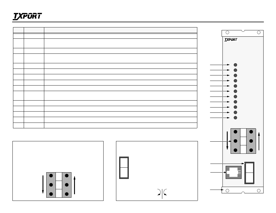
Indicator
Front Panel Description
1
POWER
This green LED lights whenever power is applied to the 1544E unit.
2
BPV/CRC
/FBE
This red LED lights (0.1 seconds minimum) for each occurrence of Bipolar Violations (BPV),
Cyclic Redundancy Check errors (CRC), or Frame Bit Errors (FBE).
3
AIS
This red LED lights if an unframed all ones signal is detected from the network or DTE.
4
LOS
This red LED flashes with Loss Of Signal from the network or the DTE.
It lights constantly if an Out Of Frame (OOF) condition is detected.
5
YELLOW
This red LED lights if a yellow alarm (far end receiver out of sync) is detected from the network or the DTE.
6
DENSITY
This red LED lights if the ones density of the received data from the DTE is less than 12.5%.
7
LINE LOOP This yellow LED lights if the unit is in a line loop condition.
8
TEST LOOP This yellow LED lights if the unit is in a local or remote test loop. It flashes if the DC loop pair is activated.
9
SET/RESET This yellow LED flashes if a set or reset code is being transmitted. It lights if a test is in progress.
10
NET FAULT This red LED flashes in conjunction with Indicators 2, 3, 4, and 5 to show that the detected fault or error is coming from
the network. It lights if a CPU fault has occurred or a fault condition exists on the network.
11
DTE FAULT This red LED flashes in conjunction with Indicators 2, 3, 4, and 5 to show that the fault or error is coming from the DTE.
12
Test Jacks
These bantam jacks provide access to the T1 line on the DTE side. Refer to the detail on this page.
13
TEST
This is a 3-position rocker switch used for performing a network test or a local loopback. See description below.
14
T-View port
Provides direct terminal access for controlling the CSU and gathering status and facility performance data.
15
Brackets
Use the 2 holes on each bracket to bolt the 1544E to the rack mount kit or wall.
1544E Front Panel
T-VIEW
1544/E
POWER
DENSITY
BPV /CRC/FBE
AIS
LOS
YELLOW
LINE LOOP
TEST LOOP
SET/RESET
TEST
14
1
2
3
4
5
6
7
8
9
12
15
TOP: The NET jack access ports break connection to the DTE and
make connection to the CSU in the direction of the network.
MIDDLE: The MON ports are used for monitoring the signals
passing through the CSU (between the DTE and the network).
BOTTOM: The DTE ports break connection to the CSU and make
connection to the DTE.
Receive signal
from the DTE
Transmit signal
to the network
Test Jack Access Ports
NET
NRM
LOC
T-VIEW PORT
13
NET FAULT
DTE FAULT
10
11
M
O
N
N
E
T
D
T
E
Transmit signal
to the DTE
Receive signal
from the network
Monitor signal
from the network
Monitor signal
from the DTE
Test Switch
TEST
NET (network test): When depressed, the CSU
loop code is transmitted for 5 seconds.
NRM (normal operation): When moved from
NET back to NRM, the CSU sends a loop down
code. When moved from LOC back to NRM, the
local loop back is removed.
LOC (local loopback): When depressed, the CSU
performs a local, bidirectional loop.
DTE NET
M
O
N
N
E
T
D
T
E
T
R
A
N
S
P
O
R
T
®