Verilink 1544E (CG) Configuration/Installation Guide User Manual
Page 2
LBO
0
7.5
15
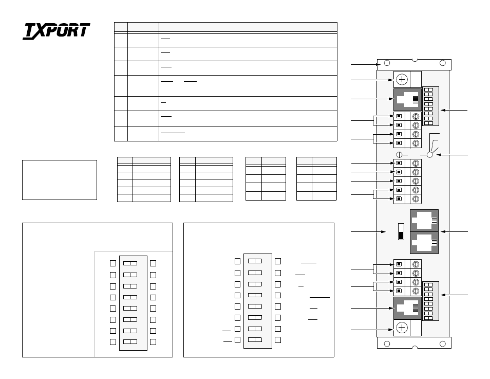
1544E Rear Panel
12
34
567
S
Right (0)
Mark your configuration selection in either the right or left box.
Then flip the switch toward your particular selection.
7
6
5
4
3
2
1
Left (1)
Test - QRS
Zeros - 15
Keep Alive - Unframed
Keep Alive - AIS
Line Code - AMI
DTE Mode - D4
Network Mode - D4
Test - Clear
Zeros - 128
Keep Alive - Framed
Keep Alive - LLB
Line Code - B8ZS
DTE Mode - ESF
Network Mode - ESF
8
W
1
12
34
56
7
S
8
W
2
I
N
O
U
T
S
E
A
L
I
N
G
ON
OFF
T-View
Ports
CSU
Config-
uration
CSU
Address
Network
Interface
Network
Output
Network
Input
Ground and
Cable Strap
Mounting
Brackets
DTE
Interface
Sealing
Current
DTE
Output
DTE
Input
8
Yellow - Transcode
Yellow - Normal
Right (0)
7
6
5
4
3
2
1
Address Switch SW1
8
MSB
LSB
various local and remote
CSUs. The information is
transmitted and received
over the CSU’s ESF Data
Link. The 8 switches are set
to a binary address code in
the range of 1 to 252.
NOTE: Each unit must
have a unique address.
Mark your address selec-
tion in the right or left box.
Then flip the switch toward
your particular selection.
This DIP Switch is used to provide up to 252 unit addresses.
The System Controller will recognize addresses from 1 to 252
and uses these addresses to poll and send commands to the
Chassis
Ground
DC
Loop
-48 VDC
VDC RTN
Configuration Switch SW2
Pos
Function
Switch SW2 Description
1
Network
Framing
ESF - Formats the network side of the CSU to Extended Superframe Format.
D4 - Formats the network side of the CSU to D4.
2
DTE Line
Framing
ESF - Formats the DTE side of the CSU to Extended Superframe Format.
D4 - Formats the DTE side of the CSU to D4.
3
Line
Code
AMI - Sets the line code for the DS-1 signal to Alternate Mark Inversion.
B8ZS - Sets the line code for the DS-1 signal to Bipolar 8 Zeros Substitution.
4/5
Network
Line Keep
Alive
S4=0 and S5=0 - Keep Alive Signal is unframed all ones.
S4=0 and S5=1 - Keep Alive signal is framed all ones.
S4=1 and S5=0 or 1 - Keep Alive signal is the activation of the line loop back.
6
Zero
Suppression
15 - ones density enforcement enabled.
50 - ones density enforcement disabled.
7
Test
Pattern
QRS - sends a QRS pattern during a network test.
Clear - traffic from DTE is passed through to the network during network test.
8
Yellow
Alarm
NORMAL - D4 Yellow Alarm is in S- bit of frame 12.
TRANSCODE - D4 Yellow Alarm is bit 2 set to 0 in all frames.
Pin
Designation
1
Input (Ring)
2
Input (Tip)
4
Output (Ring)
5
Output (Tip)
7, 8
Ground
Pin
Designation
1
Output (Ring)
2
Output (Tip)
4
Input (Ring)
5
Input (Tip)
7, 8
Ground
Ground and
Cable Strap
LBO
Sets the output signal level of
transmitted data. The Telco
should provide the proper
setting. If unsure of the exact
setting, then set to 0 dB.
Left (1)
128
64
32
16
8
4
2
1
Value
LBO Level
Network Interface
DTE Interface
Pin
Signal
1
Ground
2
Tx Data
3
Rx Data
4
Ground
T-View In
Pin
Signal
1
Ground
2
Tx Data
3
Open
4
Ground
T-View Out
NOTE: All factory default settings are
shown underlined. This unit is factory preset
for normal operation. It may be installed and
operated without any adjustment.
T
R
A
N
S
P
O
R
T
®
TxPORT Customer Service
127 Jetplex Circle
Madison, Alabama 35758
Customer Service Returns:
800 -926-0085, ext. 227
Product Technical Support
(8 a.m. to 5 p.m.)
800-285 -2755 or
205 -772 -3770, ext. 255
After Hours Hot Line:
205-551-7538