Verilink 1544N (CG) Configuration/Installation Guide User Manual
Configuration guide
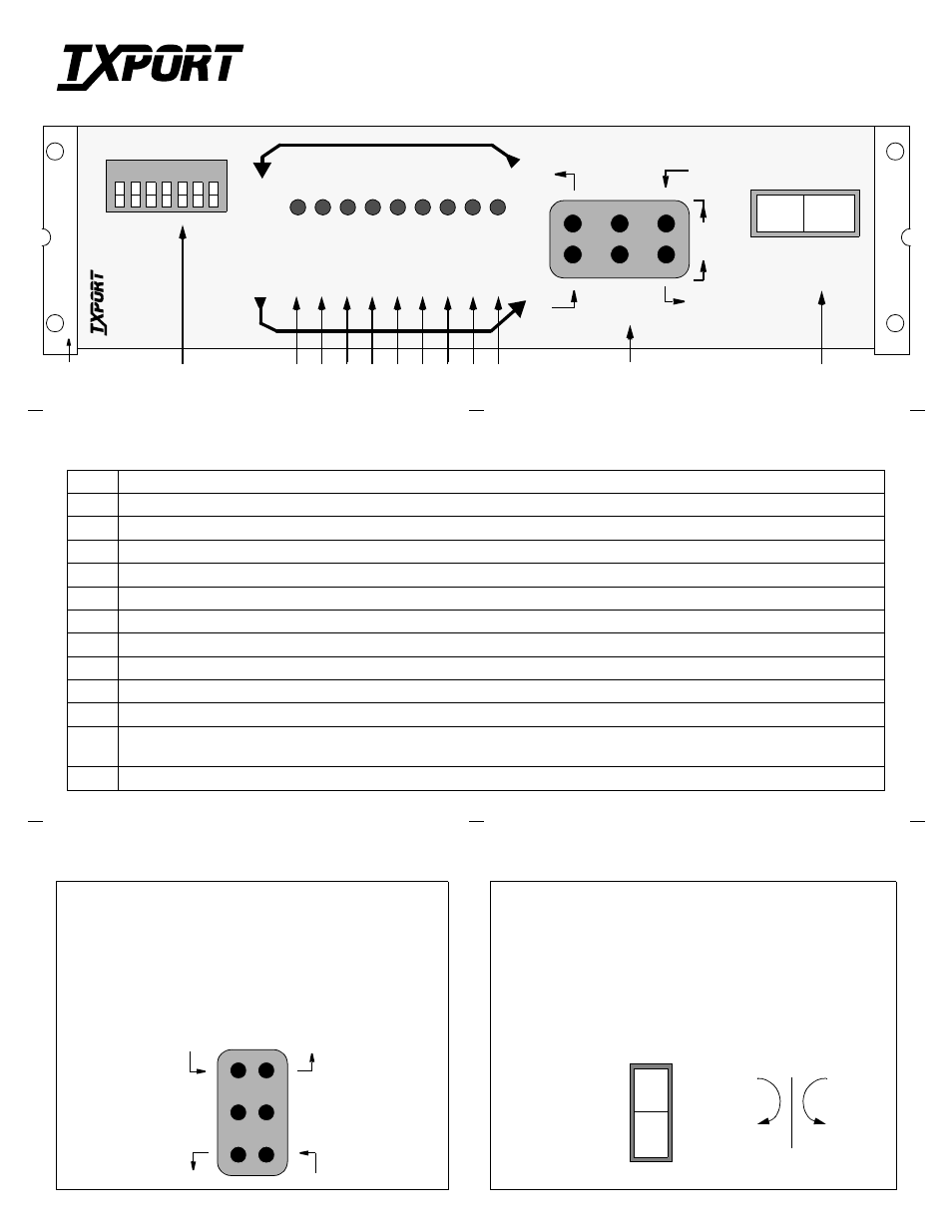
Front Panel Description
1
Brackets: Use the 2 holes on each bracket to bolt the 1544N to the rack mount kit or wall.
2
Switch SW1: This 7-position configuration switch is detailed on the reverse side of this guide.
3
POWER: This green LED lights whenever power is applied to the 1544N.
4
BPV: This red LED lights (0.1 seconds minimum) for each occurrence of bipolar violations (BPV).
5
ALL 0s: This red LED lights if no signal is detected from the network.
6
AIS: This red LED lights if an unframed all ones signal (alarm indication signal) is detected from the network or DTE.
7
LOOP: This yellow LED lights to indicate that the unit is in the Line Loopback condition.
8
DENSITY: This red LED lights if the ones density of the received data from the DTE is less than 12.5%.
9
SET: This red LED flashes when the set code is transmitted. It lights constantly if the set code is received.
10
RESET: This red LED flashes when the reset code is transmitted. It lights for 5 seconds if the reset code is received.
11
ERROR: This red LED flashes if an error is received during a network test.
12
Test Jacks: These bantam jacks provide access to the T1 line on the DTE side. The jacks allow transmit and receive toward the net-
work, toward the DTE, or monitoring of traffic between the DTE and the network. Refer to the description below.
13
Test Switch: This is a 3-position rocker switch used for performing a network test or a local loopback. Refer to the description below.
T1
CS
U
15
44
NET
W
ORK
INT
E
RF
A
C
E
1
2
3
4
5
6
7
PO
WER
DENS
ITY
BPV
ALL
0
’s
AIS
LOO
P
SET
RE
S
E
T
ERR
O
R
M
O N
DTE
M
O N
NTWK
NORMAL
TES
T
LOC
A
L
LOO
P
SW
1
TRANSPORT
®
TOP: The top 2 jack access ports break connection to the DTE
and make connection to the CSU in the direction of the network.
MIDDLE: The middle 2 ports are used for monitoring the sig-
nals passing through the CSU (between the DTE and the net-
work).
BOTTOM: The bottom 2 ports break connection to the CSU and
make connection to the DTE.
Receive signal
from the DTE
Transmit signal
to the network
Transmit signal
to the DTE
Receive signal
from the network
Monitor signal
from the network
Monitor signal
from the DTE
NETWORK TEST: When depressed, the CSU loop code is trans-
mitted for 5 seconds.
NORMAL: When moved from NTWK TEST back to NORMAL,
the CSU sends a loop down code. When moved from LOCAL LOOP
back to NORMAL, the local loop back is removed.
LOCAL LOOP: When depressed, the CSU performs a local, bidi-
rectional loop.
DTE
NET
NTWK
NORMAL
TEST
LOCAL
LOOP
13
12
8
9
10 11
7
6
5
4
3
2
T
R
A
N
S
P
O
R
T
®
1544N D4 CSU
Configuration Guide
Part Number 45- 00016
Rev 1.01
Test Jacks (12)
Test Switch (13)
1