Verilink 1544N (CG) Configuration/Installation Guide User Manual
Page 2
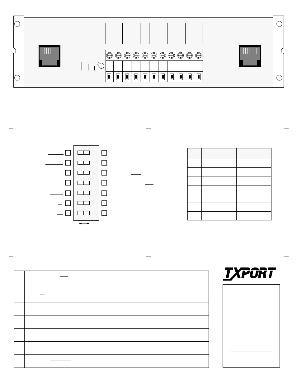
TO
NETW
ORK
FR
O
M
NETW
ORK
GR
OUND
-48 VDC
P
O
WER
–
+
FR
O
M
DTE
TO
DTE
TB1
LBO
0 d
B
7.
5 d
B
15
dB
NETW
ORK
DTE
Switch SW1 Description (front panel)
S1
Sealing Current: OFF is used where the Telco provides line power or where sealing current is not
required. ON applies sealing current to a dry (no power) Telco interface. Warning: enabling sealing
current with Telco line power present could damage the unit and/or cause improper operation.
S2
Zeros: 15 allows 15 successive zeros from the DTE before the Keep Alive mode is activated.
50 allows 50 zeros before Keep Alive is activated.
S3
Test Pattern: FRAMED indicates that the test signals (Set, Reset, and BERT) are framed.
UNFRAMED indicates that the test signals (Set, Reset, and BERT) are unframed.
S4
Bipolar Violations: AMI indicates a BPV error for each B8ZS event (if B8ZS coding is being used on
the network). B8ZS allows the CSU to be transparent to a B8ZS code coming from the network.
S5
Test Mode: CLEAR allows access to the network via test jacks to run bit error tests (effects network
tests only). BERT allows the CSU to send a bit error rate test pattern after the set signal (LOOP) is sent.
S6
Keep Alive: UNFRAMED transmits the Keep Alive signal without framing.
FRAMED adds framing information to the Keep Alive signal.
S7
Keep Alive: ALL ONES sends a consecutive sequence of all ‘1s’ back to the network.
LINE LOOP BACK sends any signal coming from the network back to the network.
NET / DTE Interface
Pin
DTE (RJ48X)
NET (RJ48C)
1
Data Out
Data In
2
Data Out
Data In
3
Not used
Not used
4
Data In
Data Out
5
Data In
Data Out
6
Not used
Not used
7 /8 Ground
Ground
NOTE: If the terminal block is to be used for DTE con-
nection, the dummy plug must be inserted into the DTE
jack. When the plug is removed, the unit is looped toward
the network. There is no loop toward the DTE.
LBO Level
Sets the output signal level of transmitted data.
The Telco should provide the proper setting. If
unsure of the exact setting, set to 0 dB.
NOTE: This unit is factory preset for normal operation. All factory default settings are shown under-
lined. The unit may be installed and operated without any further adjustment. If your particular setting
requirements are different, then mark the box which corresponds to your selection (for future reference).
7
6
5
4
3
2
1
Keep Alive - Loop Back
Keep Alive - Framed
Test Mode - Clear
Bipolar Violations - AMI
Test Pattern - Unframed
Zeros - 50
Sealing Current - On
Keep Alive - All Ones
Keep Alive - Unframed
Test Mode - BERT
Bipolar Violations - B8ZS
Test Pattern - Framed
Zeros - 15
Sealing Current - Off
1
8
1
8
Right
Left
1544N Rear Panel
Option Switch SW1 (front panel)
TxPORT
127 Jetplex Circle
Madison, Alabama 35758
Customer Service
800-926-0085, ext. 227
Product Technical Support
(8 a.m. to 5 p.m. Central)
205-772-3770, ext. 255
800-285-2755, ext. 255
Emergency After Hours
Support: 205-603-2193
Manager: 205-603-2194
T
R
A
N
S
P
O
R
T
®