Verilink 1557 (CG) Configuration/Installation Guide User Manual
Page 3
1
5
5
8
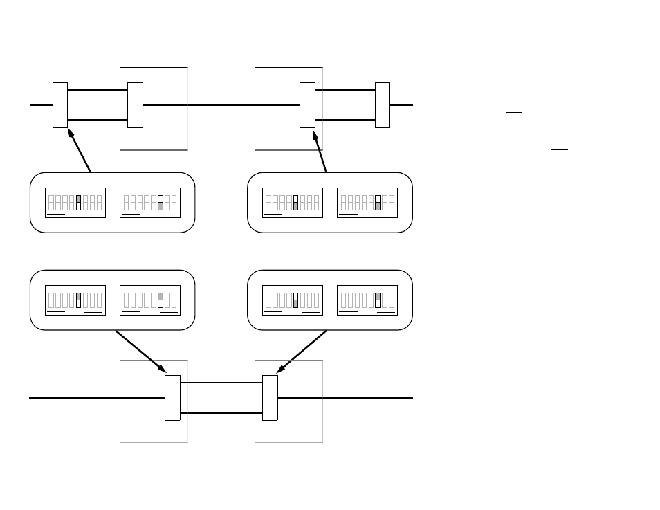
— CONFIGURATION NOTES —
• TAPS units must be configured in pairs. In each
pair, one unit must be configured as a MASTER
and one as a SLAVE.
• Each pair of TAPS units must be configured for
the same mode, NORMAL or TRANSPARENT
• A pair of TAPS units configured as NORMAL
may not be placed in the same circuit with a pair
configured as TRANSPARENT.
• It is allowed (as the diagram shows) to have two
pairs of TAPS units on the same circuit if they are
configured for NORMAL mode.
• Take note of the setting for switches S2-7 and S2-
8. These switches determine the CONFIGURA-
TION SOURCE for the 1557 card. Switch
options for Configuration Source are shown on
the front page of this document. The four choices
are explained in the 1557 Users Manual.
• A 1559 APS Manager connected to a 1557 con-
figured as a MASTER unit can monitor and do
maintenance functions on both the master unit
and its corresponding slave unit.
• A 1559 APS Manager connected to a 1557 con-
figured as a SLAVE unit can monitor only the
performance data for the slave unit. No mainte-
nance functions are available through the slave
unit.
Normal Slave
Transparent Slave
Transparent Master
Normal Master
CO #1
CO #2
CO #2
CO #1
1
5
5
7
1
5
5
7
1
5
5
8
CPE
CPE
A
B
IOC
EQUIPMENT
EQUIPMENT
ACCESS
S2-5 closed
1 2 3 4 5 6 7 8
OPEN
S3-6 open
1 2 3 4 5 6 7 8
OPEN
S2-5 closed
1 2 3 4 5 6 7 8
OPEN
S3-6 closed
1 2 3 4 5 6 7 8
OPEN
S2-5 open
1 2 3 4 5 6 7 8
OPEN
S3-6 open
1 2 3 4 5 6 7 8
OPEN
S2-5 open
1 2 3 4 5 6 7 8
OPEN
S3-6 closed
1 2 3 4 5 6 7 8
OPEN
CPE
ACCESS
A
B
EQUIPMENT
EQUIPMENT
ACCESS
CPE
IOC
B
A
1
5
5
7
1
5
5
7