Verilink 2010 Standalone (CG) Configuration/Installation Guide User Manual
2010 esf csu, Configuration guide
AC
O
S
W
AC
O
FRM
NE
T
MO
N
TO
DT
E
TO
NET
MO
N
FRM
DTE
NET
E
R
R
7
6
5
4
3
2
1
S1
NRM
L
OOP
7
6
5
4
3
2
1
S2
FA
R
E
R
R
DTE
E
R
R
L
OOP
AB
2010
ESF
CS
U
TRANSPORT
®
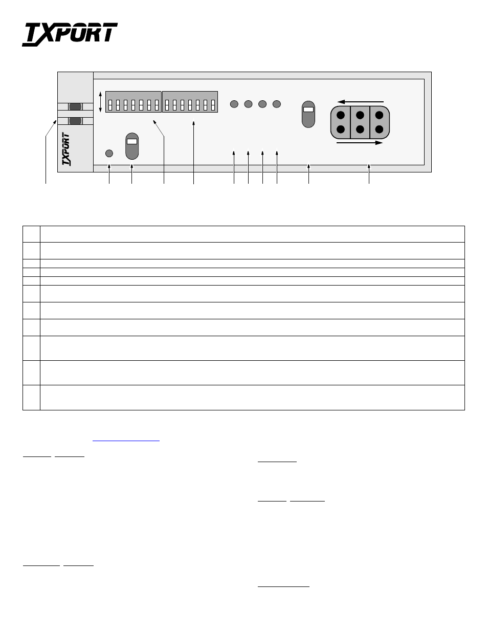
1
Status: This green LED lights when the unit is powered and operating normally. The red LED lights if the alarm card circuitry detects an alarm condition from the
FAR, NET, or DTE indicators or if an alarm threshold has been exceeded (if equipped with optional alarm card).
2
ACO: This red LED (only on units with optional alarm card) lights if the ‘alarm cut off’ switch is placed in the left ‘on’ position. This indicates that the alarm relay
contacts are disabled.
3
ACO SW: The alarm cut off switch controls the alarm relay circuitry. It is disabled in the left ‘on’ position. The right ‘off’ position enables alarm reporting.
4
Switch S1: This 7 - position DIP configuration switch is described on the reverse side.
5
Switch S2: This 7 - position DIP configuration switch is described on the reverse side.
6
Net Error: This LED lights a minimum of 0.1 second if the internal alarm circuitry detects any of the following conditions from the incoming T1 signal: 1) one or
more BPVs, 2) FBEs, 3) CRCs, 4) loss of signal / loss of sync.
7
Far Error: This LED lights a minimum of 0.1 second if the internal alarm circuitry detects a yellow alarm signal from the far end terminal equipment. This condi-
tion occurs if the far end terminal is out of sync with the T1 signal from the network.
8
DTE Error: This LED lights a minimum of 0.1 second if the internal alarm circuitry detects any one of the following conditions from the DTE: 1) one or more
BPVs, 2) FBEs, 3) CRCs, 4) yellow alarm, 5) low one’s density, 6) loss of signal / loss of sync.
9
Loop: This LED lights under the following conditions: 1) the manual loop switch is in the ‘LOOP’ position, 2) the unit receives an inband loop code for more
than 5 seconds, 3) the unit receives a FDL loop message (PLB or LLB). The LED does not light if the test switch is placed in the ‘NRM’ position or if an inband or
FDL unloop code is received.
10
Test Switch: This switch is used for local testing. In the local loop mode (LOOP), the unit loops the signal from the customer equipment (DTE in) back to the customer
equipment (DTE out). It also loops the received signal from the T1 facility (NET IN) back to the T1 facility (NET OUT). When moved back to ‘NRM’, the local
loopback is removed.
11
Test Jacks: These bantam jacks provide access to the T1 line on the DTE side as follows: The top 2 jacks break connection to the DTE and make connection to the
CSU in the direction of the network; The middle 2 ports are used for monitoring the signals passing through the CSU (between the DTE and the network); The bottom
2 ports break connection to the CSU and make connection to the DTE.
T
R
A
N
S
P
O
R
T
®
2010 ESF CSU
Configuration Guide
Part Number 45- 00047
Rev 1.02
1
SPECIFICATIONS
Network Interface
Line Rate:
1.544 Mb/s ( ±50 bps)
Line Framing:
D4 or ESF
Line Code:
AMI or B8ZS
Line Impedance:
balanced 100
Ω
(±5%)
Input Signal:
DS1, +1 to - 30 dB (ALBO)
Output Signal:
3.0 V (±15%) base-peak into 100 ¾
Line Build Out:
0, -7.5, -15, and -22.5 dB attenuation
Line Protection:
1000 V lightning, fused input/output
Jitter Control:
per TR 62411 and T1.403
Pulse Density:
per TR 62411
Equipment Interface
Line Rate:
1.544 Mb/s ( ±50 bps)
Line Framing:
D4 or ESF
Line Code:
AMI or B8ZS
Line Impedance:
balanced 100
Ω
(±5%)
Input Signal:
DSX1 to - 6 dB
Output Signal:
Selectable DSX1 level from 0 to 655
Line Protection:
1000 V lightning
Mechanical
Mounting:
desktop, wall, horizontal rack, or vertical rack
Dimensions:
1.72" W, 6.8" H, 10.5" D
Weight:
2 lbs.
Industry Standards
FCC Compliance:
Part 15, Subpart B, Class A
FCC Part 68 Reg:
FXKUSA - 75690 - DE- N
NRTL
UL 1459
CSA Certified:
LR62298
DOC /CSO3:
1653 5649 A
TR 54016
September 1989
TR62411
ANSI T1.403
Environmental
Operating Temp:
0° to 50° C (32° to 122°F)
Storage Temp:
-20° to 85° C (-4° to 185°F)
Humidity:
95% max (non - condensing)
Front Panel Description
6
10
5
3
2
11
4
7
8
9