Verilink 2100 CSU (Chassis) (CG) Configuration/Installation Guide User Manual
2100 csu, Configuration guide (chassis version)
LO
C
FA
R
AC
O
S
W
AC
O
LOOP
BPV
LOS
AI
S
DENSI
T
Y
SET
RESET
ERR
7
6
5
4
3
2
1
S2
FRM
NET
MON
TO
DTE
TO
NE
T
MO
N
FRM
DT
E
ST
A
T
U
S
2100 CSU
Configuration Guide (chassis version)
3
1
4
5
14
21
00
C
S
U
2
6
7
8
9
10 11 12
13
45 - 00033
Rev E
SPECIFICATIONS
Network Interface
Line Rate:
1.544 Mbps,
±
50 ppm (internal clock),
±
200 bps (through mode)
Line Framing:
D4 or ESF (transparent)
Line Code:
AMI or B8ZS
Input Signal:
DS1, 0 to -30 dB ALBO
Connection: RJ-48C
jack,
100
Ω
(
±
5%)
Output Signal:
3.0 V (
±
15%) base-peak into 100
Ω
Line Build Out:
0, -7.5, -15, and -22.5 dB attenuation
Line Protection:
1000 V lightning, fused input/ output
Keep Alive:
Line loopback or all ones (framed or unframed)
Jitter Control:
per TR 62411 and T1.403
Pulse Density:
15 or 175 zeros
Equipment Interface
Line Rate:
1.544 Mbps,
±
50 ppm (internal clock),
±
200 bps (through mode)
Line Framing:
D4 or ESF (transparent)
Line Code:
AMI or B8ZS
Input Signal:
DSX1 to -6 dB
Connection: RJ-48C
jack,
100
Ω
(
±
5%)
Output Signal:
Selectable DSX1 level from 0 to 655 feet in six incremental levels
Diagnostics
Loopbacks:
Line loopback on network interface
Network BERT:
1 in 8 (B8ZS), 3 in 24 (AMI), Clear test, selectable framed/
unframed
Alarms
Network Activation: BPVs, all zeros, AIS
DTE Activation:
Low density (> 15 or > 175 zeros)
Reporting:
Front panel LEDs and alarm contacts
Contact Ratings:
UL 120 mA @ 110 VAC or 110 VDC
Connection: Terminal
strip
Power
Local Power:
19 VDC to 60 VDC, 4.3 W, 15 BTU
Connection: Terminal
strip
Mechanical
Mounting:
desktop, wall, horizontal or vertical rack
Dimensions:
1.72" W, 6.8" H, 10.5" D
Weight:
2 lbs
Industry Standards
FCC Compliance:
Part 15 Subpart B, Class A
FCC Part 68 Reg:
FXKUSA-74937-DE-N
UL Approved:
E 110448
CSA Certified:
LR 98859
1
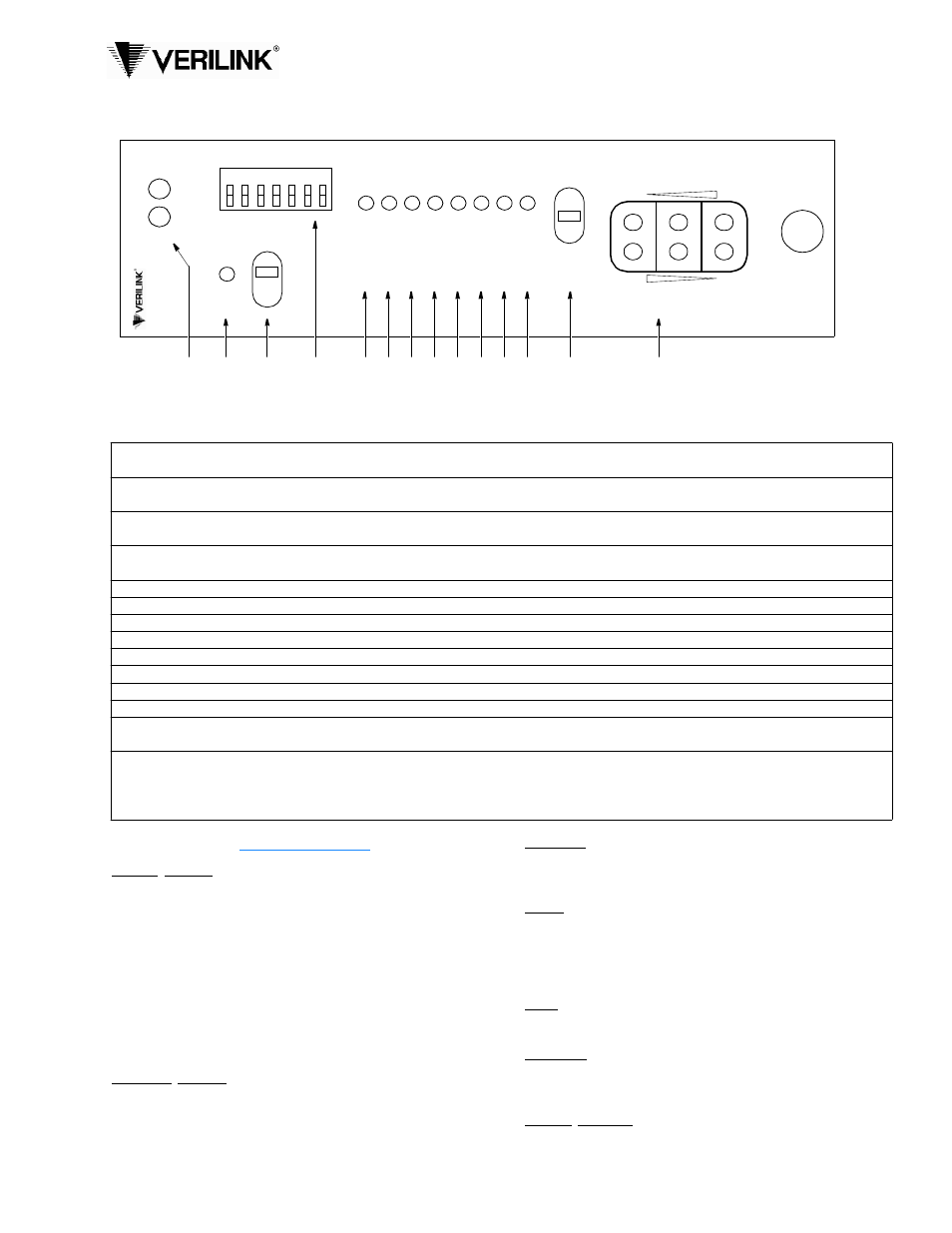
Status: The green LED lights when the unit is powered and operating normally. The red LED lights if an alarm exceeding
thresholds is detected or another type of unit failure exists.
2
ACO: This LED lights if the Alarm Cut Off switch is placed in the left On position. It indicates that the alarm relay contacts are
disabled.
3
ACO SW: This switch controls the alarm relay circuitry. The right On position disables the alarm relay contacts. The left Off
position enables the contacts to report alarm conditions.
4
Switch S2: This seven -position DIP switch is used for unit configuration. The black squares indicate the direction of factory
default settings. Refer to the switch diagram and table on back.
5
BPV: This LED lights (0.1 seconds minimum) for each occurrence of bipolar violations from the network.
6
LOS: This LED lights to indicate that a loss of signal is detected from the network.
7
AIS: This LED lights if an unframed all-ones condition (alarm indication signal) is detected from the network.
8
LOOP: This LED lights to indicate that the unit is in a line loopback condition.
9
DENSITY: This LED lights if the ones density of the received data from the DTE is less than 12.5 percent.
10
SET: This LED flashes when the set code is transmitted. It lights constantly when the set code is received.
11
RESET: This LED flashes when the reset code is transmitted. It lights for five seconds when the reset code is received.
12
ERR: This LED flashes if a BERT pattern error is received during network testing.
13
Test Switch: This three - position switch is used for performing a network test or a local loopback. The LOC setting invokes a
bidirectional loop. If the unit receives a loop code from the network, then the setting of Switch S3 - 7 applies.
14
Test Jacks: These bantam jacks provide access to the T1 line on the DTE side as follows – the top two jacks break connection to
the DTE and make connection to the unit in the direction of the network, the middle two ports are used for monitoring the signals
passing through the unit (between the DTE and the network), and the bottom two ports break connection to the unit and make
connection to the DTE.
Front Panel Description