V.35 version also available), Verilink 1051 chassis rear view – Verilink 2100 CSU (Chassis) (CG) Configuration/Installation Guide User Manual
Page 2
For future reference, all DIP switches
are provided with upper and lower
boxes to check according to the par-
ticular user selection. Factory default
settings are shown underlined.
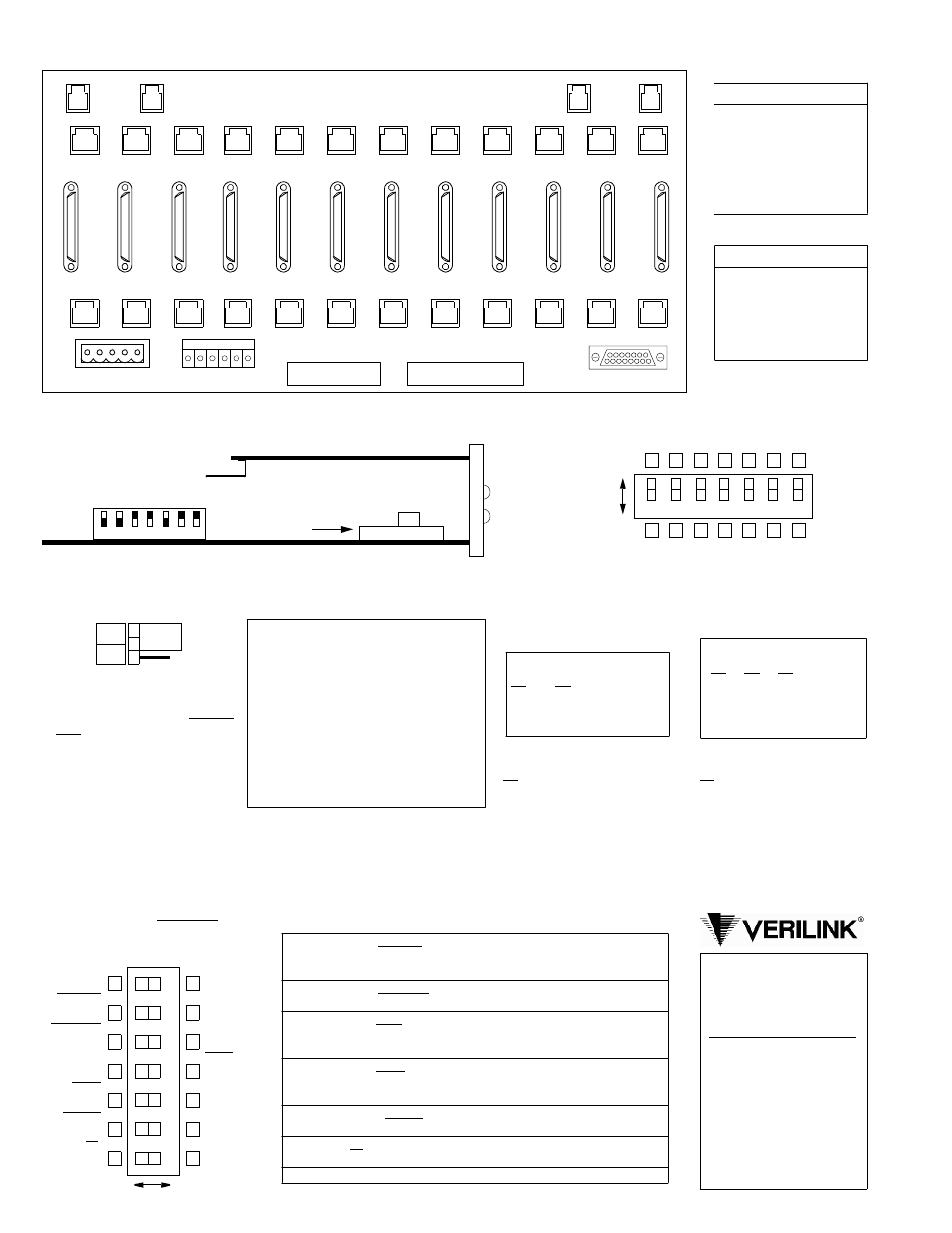
Verilink 1051 Chassis Rear View
(V.35 version also available)
Pin T1 DTE T1 NET
1
Data Out
Data In
2
Data Out
Data In
3
Not used
Not used
4
Data In
Data Out
5
Data In
Data Out
6
Not used
Not used
7, 8 Signal Gnd Signal Gnd
Pin NMS In
NMS Out
1
Not Used
Not Used
2
Signal Gnd Signal Gnd
3
Data Out
Data Out
4
Data In
Not Used
5
Signal Gnd Signal Gnd
6
Not Used
Not Used
Chassis Connections
T1 DTE
1
2
3
4
5
6
7
8
9
10
11
12
( B )
NMS
IN
( B )
NMS
OUT
12
High Speed DTE
11
10
9
8
7
6
5
4
3
2
1
T1 NET
TB1
TB2
ENET
( A )
NMS
IN
( A )
NMS
OUT
1
2
3
4
5
6
7
8
9
10
11
12
TB1
TB2
Right
Left
Keep Alive
Keep Alive
Test Mode
Test Code
Test Pattern
Zeros
Reserved
Keep Alive
Keep Alive
Test Mode
Test Code
Test Pattern
Zeros
7
6
5
4
3
2
1
All Ones
Unframed
BERT
B8ZS
Framed
15
Loop Back
Framed
Clear
AMI
Unframed
175
Switch S2 (front panel)
Switch S3
7
6
5
4
3
2
1
Dn
Up
S3- 1
S3- 2
LBO Level
Dn
Dn
0 dB
Dn
Up
- 7.5 dB
Up
Dn
- 15.0 dB
Up
Up
- 22.5 dB
Network LBO: Sets the output
signal level of transmitted data.
The telco should provide the
proper setting. If unsure of the
exact setting, set to 0 dB.
S3- 3 S3- 4 S3- 5
Distance
Up
Up
Dn
0' - 133'
Dn
Dn
Up
134'- 266'
Up
Dn
Up
267'- 399'
Dn
Up
Up
400'- 533'
Up
Up
Up
534'- 655'
S3- 7 During Remote Loop
Up: AIS to DTE
Dn: Network data to DTE
DTE LBO: The transmit output
level is selectable according to
the cable length from the CSU
DTE port to the T1 equipment.
S3- 6 Line Code
Up: Line code transparent
Dn: DTE AMI –> NET B8ZS
7
Keep Alive: All Ones sends a consecutive sequence of all ones back to
the network. Loopback sends any signal coming from the network
back to the network.
6
Keep Alive: Unframed transmits the Keep Alive signal without
framing. Framed adds framing information to the Keep Alive signal.
5
Test Mode: Clear allows network access via test jacks to run bit error
tests (affects network test only). BERT allows the CSU to send a bit
error rate test pattern after the set signal (LOOP) is sent.
4
Test Code: B8ZS allows the CSU to be transparent to a B8ZS code
coming from the network and sets the test signals to B8ZS. AMI shows
a BPV error for each event.
3
Test Pattern: Framed indicates that the test signals (Set, Reset, and
BERT) are framed. ‘Unframed’ indicates the test signals are unframed.
2
Zeros: 15 allows 15 successive zeros from the DTE before the Keep
Alive mode is activated. 175 allows 175 zeros before activation.
1
Reserved.
Switch S2 Description
This three - pin jumper straps the
ACO alarm contact. Position jump-
er over pins 1 and 2 for normally
open operation (closes on alarm) or
over pins 2 and 3 for normally
closed operation (opens on alarm).
NO
NC
1
2
3
Alarm Relay
The optional ACO /alarm card monitors the
alarm indicators for an alarm active or an
alarm clear condition and provides closure
contact points on the rear panel. The corre-
sponding front panel LED lights when an
alarm condition is detected on the four dif-
ferent conditions shown below.
1)
Network AIS (all ones)
2)
Network LOS (all zeros)
3)
Network BPVs
4)
DTE ones density
Optional Alarm Card
Circuit Board View
7
6
5
4
3
2
1
2100
Switch S3
Alarm Relay
front
panel
Factory set -
TX
KX
do not change
Optional Alarm Card
Black squares indicate direction
of factory default switch settings
Reserved
950 Explorer Blvd.
Huntsville, AL 35806
800 -926-0085
Product Technical Support
(8 a.m. to 5 p.m. Central)
800 -285- 2755 or
256 -327-2255
E-mail:
Online:
www.verilink.com