Switch s2, Rear panel pinouts, Rear panel – Verilink 3131 (CG) (CG) Configuration/Installation Guide User Manual
Page 2: Switch s1, Data port bit rates, Data port pinouts
Switch S2
S2 - 1 through S1-5:Determine the data
port bit rate. Refer to the Data Port Bit
Rates chart for configuration settings.
S2 - 6: Sets the channel assignment mode.
Dn: Contiguous
Up: Alternate
S2 - 7: Sets the data port rate multiplier.
Dn: N x 64 k
Up: N x 56 k
S2-8: Sets the power-up mode.
Dn: Switches Up: RAM
S2 -9 S2 - 10
SUPV Port Rate
Up
Up
1.2 kbps
Dn
Up
2.4 kbps
Dn
Dn
9.6 kbps
Up
Dn
19.2 kbps
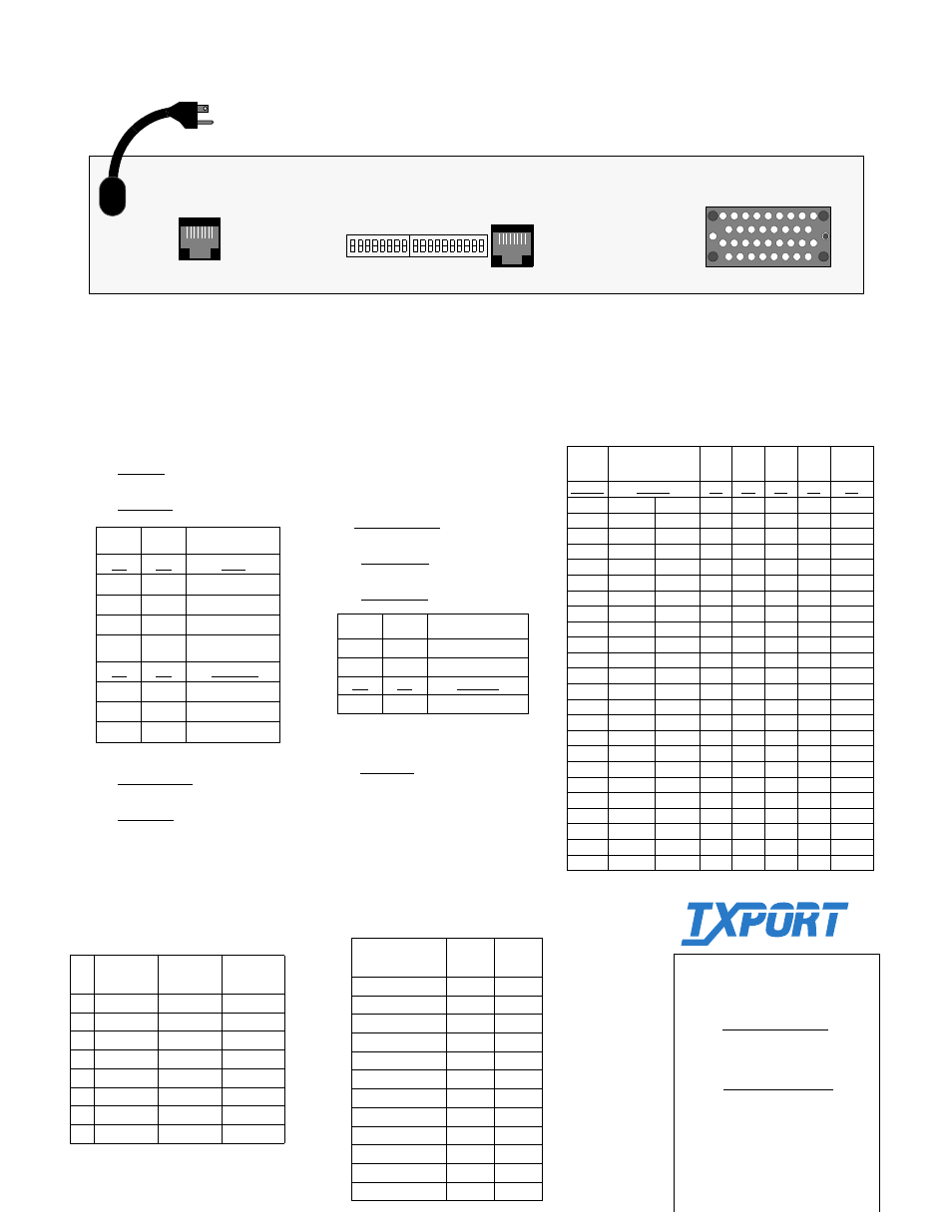
Rear Panel Pinouts
Pin
SUPV
Terminal
SUPV
Modem
Network
1
DCD Out
DTR Out
Data In
2
CTS Out
RTS Out
Data In
3
Frame Gnd
Frame Gnd
Not Used
4
Data Out
Data Out
Data Out
5
Data In
Data In
Data Out
6
Signal Gnd
Signal Gnd
Not Used
7
RTS In
CTS In
Chassis Gnd
8
DTR In
DCD In
Chassis Gnd
Factory defaults for all switch settings are
shown underlined.
Switch S2-9 and S2-10 must be set before
powering the unit.
Rear Panel
TxPORT
127 Jetplex Circle
Madison, Alabama 35758
Customer Service
800- 926-0085, ext. 2227
Switch S1
S1 - 1: Set the network line framing.
Dn - ESF
Up - D4
S1 - 2: Sets the network line coding.
Dn - B8ZS
Up - AMI
S1 - 7: Test button loop code.
Dn: LLB code
Up: V.54 code
S1 - 8: Test button operational mode.
Dn: BERT
Up: Clear loop
S1 - 3
S1- 4
Network LBO
Dn
Dn
0 dB
Up
Dn
- 7.5 dB
Dn
Up
- 15.0 dB
Up
Up
- 22.5 dB
S1 - 5
S1 - 6
Timing Source
Dn
Dn
Network
Up
Dn
Internal
Dn
Up
Port 1 EXC
Up
Up
N/A
Data Port Bit Rates
# of
DSOs
S2-7
Up Dn
S2-1 S2-2 S2-3 S2-4 S2- 5
Disable
Disable
Dn Dn Dn Dn Dn
1 56
kb/s
64
kb/s Up Dn Dn Dn Dn
2
112
128
Dn
Up Dn Dn Dn
3
168
192
Up Up Dn Dn Dn
4
224
256
Dn
Dn Up Dn Dn
5
280
320
Up Dn Up Dn Dn
6
336
384
Dn
Up Up Dn Dn
7
392
448
Up Up Up Dn Dn
8
448
512
Dn
Dn Dn Up Dn
9
504
576
Up Dn Dn Up Dn
10
560
640
Dn
Up Dn Up Dn
11
616
704
Up Up Dn Up Dn
12
672
768
Dn
Dn Up Up Dn
13
728
832
Up Dn Up Up Dn
14
784
896
Dn
Up Up Up Dn
15
840
960
Up Up Up Up Dn
16
896
1024
Dn
Dn Dn Dn Up
17
952
1088
Up Dn Dn Dn Up
18
1008
1152
Dn
Up Dn Dn Up
19
1064
1216
Up Up Dn Dn Up
20
1120
1280
Dn
Dn Up Dn Up
21 1176
1344
Up Dn Up Dn Up
22
1232
1408
Dn
Up Up Dn Up
23
1288
1472
Up Up Up Dn Up
24
1344
1536
Dn
Dn Dn Up
Up
Data Port Pinouts
Common Name
DB25
25- pin
V.35
34-pin
Frame Ground
1
A
Signal Ground
7
B
Transmit Data
2, 14
P, S
Receive Data
3, 16
R, T
Request to Send
4, 19
C
Clear to Send
5, 13
D
Data Set Ready
6, 22
E
Data Term Ready
20, 23
H
Data Carrier Detect
8, 10
F
Transmit Clock
15, 12
Y, AA
Receive Clock
17, 9
V, X
Terminal Timing
24, 11
U, W
SUPV
NET
DATA PORT 1
115 VAC
60 HZ
S1
S2
Technical Support
(8 a.m. to 5 p.m. Central Time)
Toll Free:888-4TxPORT
800-285-2755 (and af-
ter-hours emergencies)
Locally: 205-772-3770
e-mail:
1
8 1
10
T
R
A
N
S
P
O
R
T
®