Verilink 4010 DDS CSU/DSU (Chassis) (CG) Configuration/Installation Guide User Manual
4010 dds csu/dsu, Configuration guide, Specifications
1
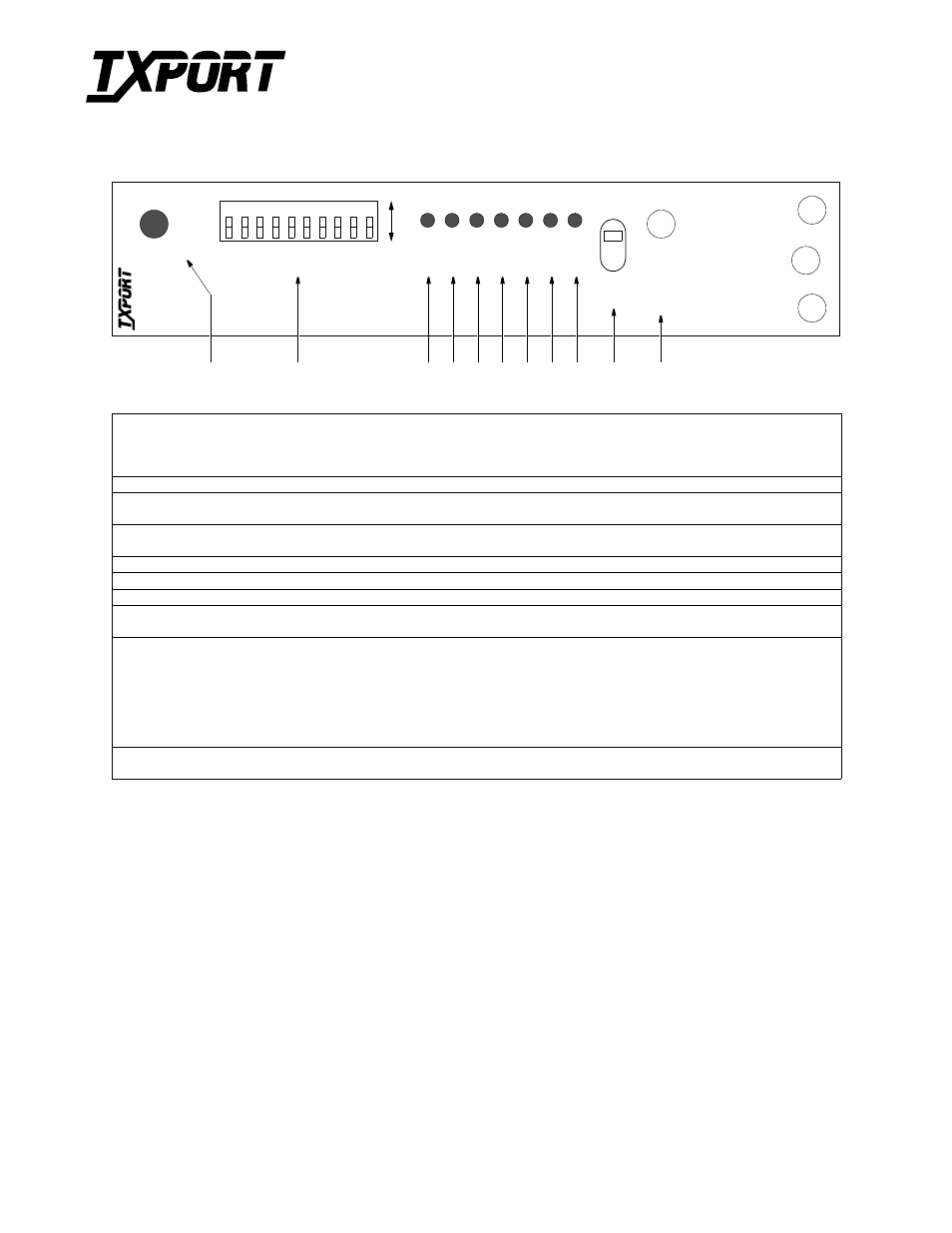
In Service: This three-color IN SERVICE LED indicates the DDS loop receiver’s operating status as follows:
GREEN: Indicates DDS signal at the receiver (either customer data or zero suppression).
AMBER: Indicates DDS signal is still present, but received data is idle or out of service.
RED: Indicates an insufficient signal for the DDS receiver to operate properly.
2
Switch SW1: This 10-position LED switch is described on the reverse side.
3
TXD: This green transmit-data LED lights when the data lead is a mark and is off when the data lead is a space.
Therefore, the LED varies from full intensity to off, depending on the relative number of marks and spaces.
4
RXD: This green receive-data LED lights when the data lead is a mark and is off when the data lead is a space.
Therefore, the LED varies from full intensity to off, depending on the relative number of marks and spaces.
5
RTS: This green request-to-send LED lights when circuit CA is in the ON state at the DSU interface.
6
CTS: This green clear-to-send LED lights when circuit CB is in the ON state at the DSU interface.
7
DCD: This green receive-line-signal-detector LED lights when circuit CF is in the ON state at the DSU interface.
8, 9 V.35 and 232: The green V.35 LED is ON when the DTE electrical interface is set to V.35. The green 232 LED is ON when
the interface is set to RS-232. If neither light is on, the configuration switches are set incorrectly.
10
Test Switch: This three-position switch operates as follows:
The LOC position places the unit in a local-loop mode. Data from the DTE is looped back to the DTE. Data from the
network is looped back to the network.
The FAR position initiates an automated V.54 remote loop and BERT sequence of assigned data channels. The TEST LED is
green if the test is successful (the far-end unit loops and returns the data error free with the V.54 code). If errors are detected, the
TEST LED is red.
The center position deactivates the loop codes for normal operation.
11
LOOP TEST: This LED remains amber if there is a local loop or a remote loop. The LED turns red if the V.54 BERT test
fails or green if the V.54 BERT test passes.
T
R
A
N
S
P
O
R
T
®
Specifications
Network Interface
Line Rate:
2.4, 4.8, 9.6, 19.2, 28, 38.4, 56, and 64 kbps
Line Code:
AMI
Line Impedance:
balanced 135
Ω
Input Signal:
+1 to -40 dB (ALBO)
Output Signal:
3.0 V (±15%) base-peak into 135 ¾,
1.5 V (±15%) at the 9.6 kbps line rate
Line Protection:
1000 V lightning, input and output
Power
Power:
-48 VDC (± 10%), 50 mA max,
3 watts, 10 BTU max
Connection:
Powered through chassis
Mechanical
Mounting:
1051 nest mount chassis
Dimensions:
6.8" H, 1.75" W, 10.5" D
Weight:
2 lbs.
Industry Standards
FCC Compliance: Part 15 Subpart B, Class A
FCC Part 68 Reg: FXKUSA-22989-DE-N
NRTL:
CSA Certified:
AT&T TR 62310
AT&T TR 41450
Environmental
Operating Temp:
0° to 50°C (32° to 122°F)
Storage Temp:
- 20° to 85°C (- 4° to 185°F)
Humidity:
95% max (non - condensing)
4010 DDS CSU/DSU
Configuration Guide
Part Number 45-00084
Rev 1.01
Front Panel Description
4010 Front Panel
TX
D
7
6
5
4
3
2
1
SW1
LO
C
FA
R
IN S
E
R
V
IC
E
AB
DDS
CSU
/DSU
1
40
10
8
9
10
RXD
RT
S
CT
S
DCD
V.
3
5
232
L
O
OP
T
E
S
T
2
3
4
5
6
7
8
9
10
11
TRANSPORT
®