Verilink DDS Lite (CG) Configuration/Installation Guide User Manual
Quick start guide, Indicators, Loopbacks
Indicators
Network
This three-color indicator shows the receiver’s
operating status. Green indicates a signal at the
receiver (either customer data or zero suppres-
sion). Amber indicates signal is present, but re-
ceived data is idle or out of service. Red
indicates an insufficient signal for the receiver
to operate properly.
Tx Data
This three-color indicator shows the status of
the transmitted data. Green indicates marks.
Red indicates spaces. Amber indicates alternate
marks and spaces.
Rx Data
This three-color indicator shows the status of
the received data. Green indicates marks. Red
indicates spaces. Amber indicates alternate
marks and spaces.
Loop Test
This indicator show the loop status of the unit.
Amber indicates the unit is in loop mode.
When the indicator is Off, the unit is not in
loopback.
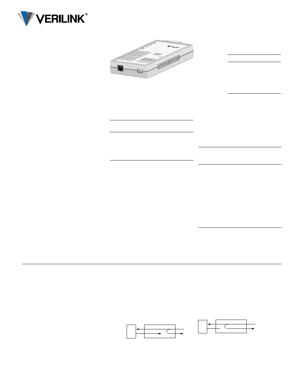
Loopbacks
Channel Loop
This loop
is acti-
vated by
the reversal of the simplex, 20 mA sealing cur-
rent. This is a unidirectional loop that ignores
the DSU transmit data and retransmits the re-
ceived DDS data. Receive data is unaffected
and circuit CF is forced Off.
Data Set Loop (Non-latching)
This loop is activated by the receipt of at least
four consecutive loop commands and remains
looped as long as each third pattern byte is the
loop command. It returns to normal operation
after at least four pattern bytes that are not the
loop command. This is a unidirectional loop
that retransmits the DSU received data on the
DSU transmit data. Receive data is unaffected
and circuit CF is Off.
V.54 Channel Loop (Annex B: RDL)
This loop is activated by the receipt of the V.54
loop command. This loop is unidirectional and
returns the DSU receive data to the DSU trans-
mit data, and subsequently the DDS transmit
data. Receive data is unaffected.
DTE
NET
DTE
NET
Note: For more information about the DDS Lite,
see the reference manual, part number
34-00295, on the User Documentation CD or at
www.verilink.com.
Specifications
Network Interface
Line Rate:
2.4, 4.8, 9.6, 19.2, 28, 38.4,
56, and 64 kbps
Line Code:
AMI
Line Impedance: Balanced 135
Ω
Input Signal:
+1 to
−
40 dB (ALBO)
Output Signal:
3.0 V (±15%) base-peak
into 135
Ω
,
1.5 V (±15%) at the 9.6
kbps line rate
Line Protection: 1000 V lightning, input/
output
Mechanical
Mounting:
desktop or wallmount
Dimensions:
1.25" H, 3.50" W, 5.75" D
Weight:
1 pound
Power Source
External:
Input: 115 VAC
Output: 9 VAC, 400 mA, min.
Industry Standards
FCC Compliance: Part 15 Class A
Subpart B, Part 68
U.S. Safety:
UL 1950
Canadian Safety: CSA C22.2 No. 950- 95
Industry Canada: CS-03, Issue 8
Bellcore
GR-1089-CORE
Environmental
Operating Temp: 0° to 50°C (32° to 122°F)
Storage Temp:
−
20° to 70°C
(
−
4° to 158°F)
Humidity:
95% max (non-condensing)
Pre-Installation Information
All direct connections to DDS lines must be
made using standard plugs and jacks.
Before connecting the unit, inform the
local telephone company of the following
information.
Wallmount Installation
Using Screws
1 Select a place close to a 115 VAC outlet with
clearance for the signal and power cables.
The indicators and switches should be easily
accessible.
2 Vertically place two #6 screws 3-13
⁄
32
inches apart at the selected place. Leave the
screws out about an eighth of an inch.
3 Place the upright unit over the screws until
the holes engage and slide the unit down un-
til it locks.
Connections
DDS Network Connection
The network
DDS facility
interface is
an RJ- 48C
(8- pin) modu-
lar jack with the
following
pinout.
RS-232 Port Connection
The RS-232 connector is a standard DB-25 fe-
male, configured as a DCE port.
The RS-232 pin assignments are shown below.
Only circuits used by the unit are listed. All un-
balanced bipolar inputs and outputs meet RS-
232C physical and electrical specifications. The
asynchronous mode is ITU V.22 compliant.
Power
Plug the connector from the power supply into
the unit. Plug the transformer into an appropri-
ate outlet. This applies power to the unit.
Port ID
REN/
SOC
kbps FIC
USOC
2.4
4.8
9.6
38.4
56
64
6.0 N 2.4
4.8
9.6
38.4
56
64
04DU5-24
04DU5-48
04DU5-96
04DU5-38
04DU5-56
04DU5-64
RJ -48S
jack
NETWR
Tx DATA
Rx DATA
LP TEST
DDS Lite
NET
PWER
B
A
B
A
A
A
B
B
B
A
S2
S
RS232-DCE
CA
RT
2
(AS
NC
)
S2-3
S2-2
Bits
B
B
A
A
B
B
A
A
B
B
B
B
A
A
A
A
.
4.
2.
.
.
.5
.4
.3
B
A
B
A
B
A
B
A
2.4
kb
s
4. k
bs
. kb
s
.2 k
bs
2. k
bs
3.4
kb
s
5. k
bs
4. k
bs
NE
TW
R
BIT
RA
TE
RTS-to-CTS
Delay (ms)
S-3
S-2
S-
CA
RT
PS
ITIN
-3
PS
ITIN
4
PS
ITIN
5
PS
ITIN
PS
ITIN
PS
ITIN
US
E C
AR
T
V.5
4 L
P
DA
TA
CIR
CU
IT A
SS
UR
AN
CE
CT
S
RT
S-T
-CT
S D
ELA
EN
AB
LE
NR
MA
L
NR
MA
L
NR
MA
L
DIS
AB
LE
INV
ER
TED
N
RC
ED
2
PS
ITIN
PS
ITIN
23
PS
ITIN
4
PS
ITIN
5-
DA
TA
US
E C
AR
T 2
AIN
RA
NE
NT
US
ED
SN
C
-2.5
T2.
3
AS
NC
-2.5
T.
N
S2
A
B
UN
CT
IN
S
A
B
UN
CT
IN
N
2
3
4
5
N
2
3
4
5
Circuit RS-232
Signal Function
(Note: All other
pins are open.)
DCE
101
1 Frame
Ground
Gnd
102
7 Signal
Ground
Gnd
103
2 Transmit
Data
In
104
3 Receive
Data
Out
105
4
Request To Send
In
106
5
Clear To Send
Out
107
6 Data
Set
Ready
Out
109
8 Data
Carrier
Detect Out
114
15
Transmit Clock
Out
115
17 Receive
Clock
Out
Pin Assignment
1
Network Transmit Out
2
Network Transmit Out
3–6 Not Used
7
Network Data In
8
Network Data In
45-00150
2.0
DDS Lite
Quick Start Guide