Configuration, Warranty, Returning products – Verilink DDS Lite (CG) Configuration/Installation Guide User Manual
Page 2
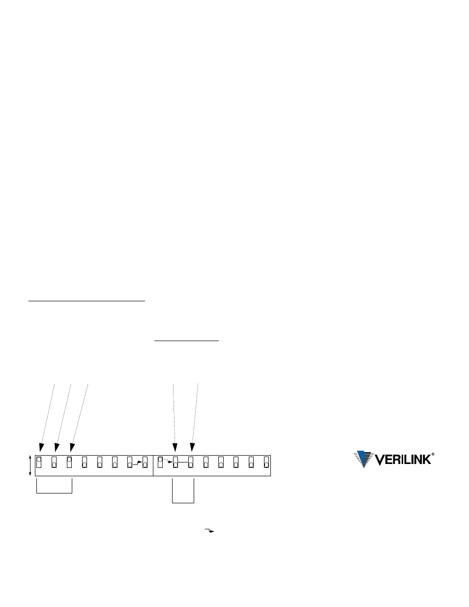
Configuration
On power up, the unit configures to the hard-
ware settings of option switches SW1 and
SW2. Changes to these settings take effect after
resetting the unit by removing and then reap-
plying power. The unit then cycles through its
LEDs and reads the new configuration.
These switches provide the following
configuration parameters.
Network Bit Rate Select
Positions SW1-1, SW1-2, and SW1-3 are
used to set the network bit rate. Refer to the ta-
ble shown in the upper left of the figure to de-
termine the switch settings for a particular bit
rate. RTS-to- CTS delays double when position
SW1-8 is in the B position.
V.54 Loop Operation
Position SW1-4 is used to enable or disable
V.54 loop operation.
Data Polarity
SW1-5 is used to determine whether data bits
are inverted. In the A position, marks equal
pulses. In the B position, spaces equal pulses.
Receipt of OOF, OOS, idle, or loop codes
forces the DSU data to all marks (A position)
or spaces (B position).
Circuit Assurance
When SW1- 6 is in position B, the status of CF
(receive line signal detector) and CA (request
to send) controls the output CB (clear to send).
If either CA or CF is Off, CB is Off. If CA and
CF are On, CB is On.
CTS Control
When SW1- 7 is in position B, CTS is forced
On regardless of the RTS input status. In the A
position, the delays are determined by SW1-8.
RTS-to-CTS Delay
When SW1- 8 is in the A position, the RTS-to-
CTS delay is as shown in the table shown in
the upper left of the figure. In the B position,
the delays double.
Synchronous/Asynchronous Data
When SW2-1 is in the A position, the unit op-
erates in Synchronous mode. This switch must
be in position B for switches SW2-2 and SW2-
3 to function. When in position B, the unit op-
erates in Asynchronous mode. In Asynchro-
nous mode, data functions at 2.4, 4.8, 9.6, 19.2,
and 38.4 kbps.
Asynchronous Word Length
Switches SW2-2 and SW2-3 are set to match
the number of bits that make in each word of
the asynchronous data. Refer to the table
shown in the upper right of the figure.
Signalling Rate Range
Switch SW2-4 is set to match the ranges pro-
vided by the service provider.
Not Used
Switches S2-5, S2-6, S2-7, and S2-8 are not
used.
145 Baytech Drive
San Jose, California 95134
127 Jetplex Circle
Madison, Alabama 35758
(800) 837-4546
www.verilink.com
FAX-On-Demand
(800) 957-5465
Technical Assistance Center
(800) 285-2755
2
5
4
3
1
3
1
4
2
B
A
Rate
(kbps)
SW
1-1
SW
1- 2
SW
1- 3
RTS-to-CTS
Delay (ms)
2.4 B
B
B
8.0
4.8 A
B
B
4.0
9.6 B
A
B
2.0
19.2 A
A
B
1.0
28.0
B
B
A
0.8
38.4 A
B
A
0.5
56.0 B
A
A
0.4
64.0 A
A
A
0.3
8
6
7
V.
5
4
D
is
ab
le
d
V.
5
4
L
o
o
p
En
a
b
le
d
Data Norma
l
Data In
v
erted
Channel
Bit Rate
Async
Word
Length
Circu
it Ass
u
ran
ce
On
Ci
rc
u
it Assu
ran
ce O
ff
CTS
F
o
rc
ed
On
CT
S No
rma
l
RT
S
-t
o
-C
T
S
D
el
ay
×2
R
T
S
-to
-C
TS
De
la
y
Norma
l
S
y
nch
ron
ous
Dat
a
Asyn
ch
rono
us Dat
a*
Bits SW2-2 SW2-3
8
A
B
9
B
B
10
A
A
11
B
A
* Asynchronous data
does not function at
28, 56, and 64 kbps.
5
8
6
7
no
t us
ed
no
t use
d
no
t use
d
no
t use
d
no
t use
d
no
t us
ed
no
t us
ed
no
t us
ed
The symbol
indicates that the
switch pointed to does not function
unless the opposite end of the arrow
is in the position shown. For
example, SW1-8 functions only
when SW1-7 is in the A position.
Basic Ran
g
e
(
−
2.5
to 1.
0%
)
Ex
te
nd
ed
R
ang
e
(
−
2.
5 t
o
2.
3%
)
Warranty
Verilink's product warranty covers repair or re-
placement of all equipment under normal use
for a five-year period from date of shipment.
Replacement products may be new or recondi-
tioned. Any replaced or repaired product or part
has a ninety (90) day warranty or the remainder
of the initial warranty period, whichever is
longer. Our in-house Repair Center services on
a standard 10-workday-turnaround basis.
Returning Products
A product must be assigned a Return Materials
Authorization (RMA) number before it is sent
to Verilink for repair. An RMA number is is-
sued by Verilink Customer Service at (800)
926-0085, ext. 2282.