Verilink PRISM 3010 (CG) Configuration/Installation Guide User Manual
3010 v, Oice, Odules
3010 V
OICE
M
ODULES
45-00136
7.0
Configuration Guide
Card Installation
Note: Only two FXO or FXS cards can
be used in the standard 3060 chassis
(p/n F-3060-001- -xxxx). Four FXS or
FXO cards can be used in the 3060
chassis with the enhanced power sup-
ply (p/n F-3060- 001A -xxxx).
Option modules may be damaged by
static electricity. Use ESD (electro-
static device) precautionary measures
such as wearing static grounding
straps and storing modules in the sup-
plied antistatic bags.
Warning: To prevent electric shock or
damage to the unit, turn the rear panel
power switch OFF before removing or
installing any option modules.
To add a module to an empty slot,
remove the cover plate which is held in
place by two screws. Carefully slide
the new card along the guides with the
component side facing down. Push the
board in until the faceplate rests
against the rear panel. Replace the
screws.
If resistance is encountered when
inserting the card, remove the card and
verify that there are no obstructions in
its path. Also check for bent or dam-
aged pins in the connectors of the
module and chassis.
Voice Card Type Part Number
6- Port FXS F-3010-200A-111
6- Port E&M F-3010-200--112
(Types
I,
II,
III)
6- Port FXO F-3010-200A-113
6- Port E&M
F-3010-200--114 (Types I, II, III, IV, V)
Specifications
Connector: AMP
50 - pin
(25
pairs),
female
Encoding: PCM
six
ports
per
card
Noise: <
20
dBrnc
Signal to Noise: > 35 dB
Freq. Response: 300 Hz to 3 kHz (± 0.5 dB)
Power: Internal
(FXS
and
FXO)
External (4 -Wire E&M: -48 VDC)
Signalling:
See the Signalling section on the
other side.
Warranty: 5
Years
Operating Temp: 0° to 50°C (32° to 122°F)
Storage Temp:
- 20° to 85°C (- 4° to 185°F)
Humidity:
95% max (non -condensing)
2-Wire FXS Connection
Pair
Pin
# Color
Function
1 26
T
1 R
White / Blue
Blue / White
Circuit #1
2 27
T
2 R
White / Orange
Orange / White
Circuit #2
3 28
T
3 R
White / Green
Green / White
Circuit #3
4 29
T
4 R
White / Brown
Brown / White
Circuit #4
5 30
T
5 R
White / Slate
Slate / White
Circuit #5
6 31
T
6 R
Red / Blue
Blue / Red
Circuit #6
Voice Card Connections
The 3010 voice cards are used to interface up to six pieces
of analog telephone equipment (telephones or key equip-
ment) to a T1 facility.
The 4 -Wire E&M requires an external -48 VDC source
(42 to 60 VDC at 300 mA). The external source is used
for relay activation and Type 2 signalling.
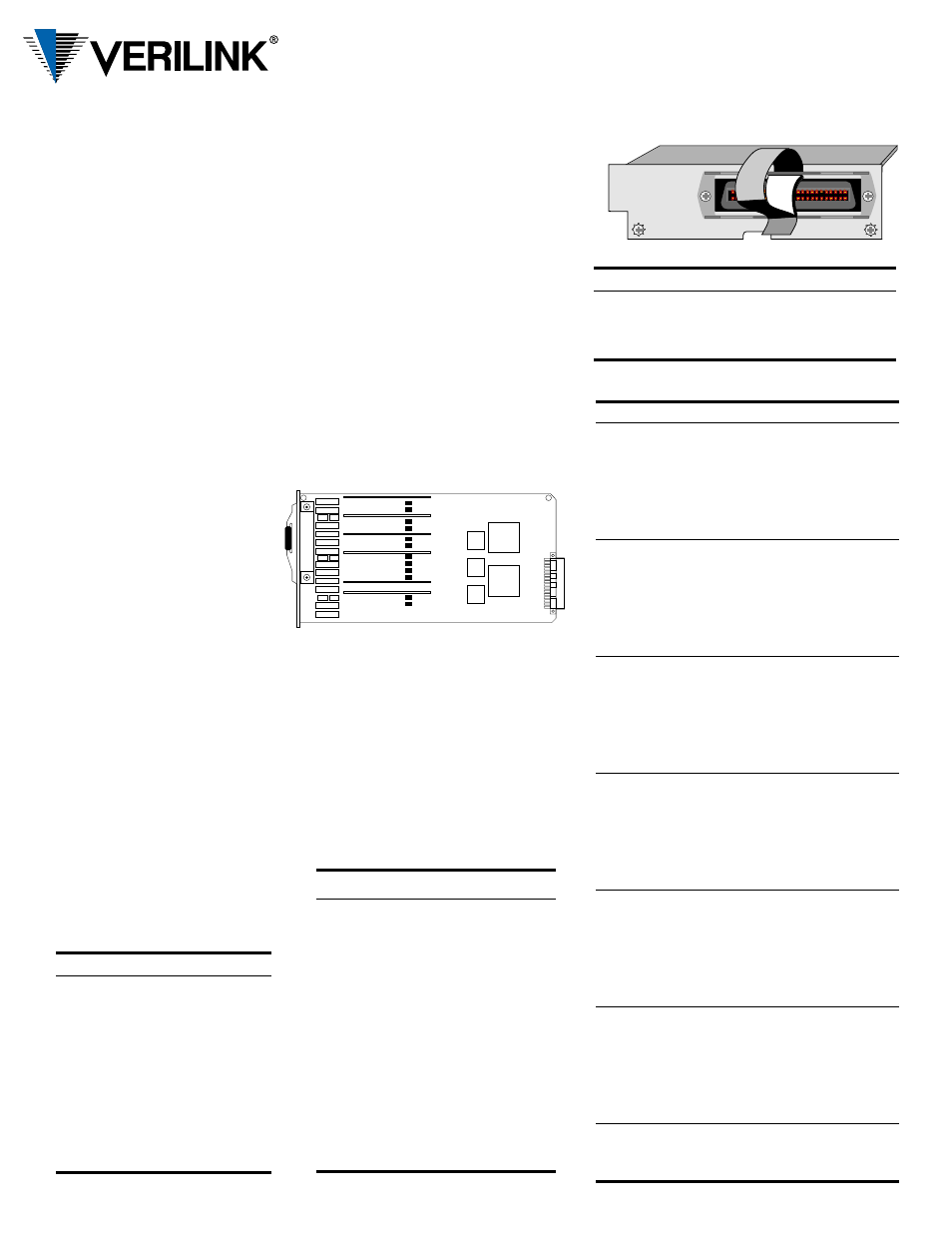
Connection to each type of voice card is made through a
rear panel 25 - pair female connector, retained by a hook-
and-loop-fastener strap. Refer to the tables on this page
for connection information.
The PRISM 3010 six - port voice card is
the solution for integrating analog voice
applications into fractional or full T1
services. Hardware switch settings are
not required on PRISM modules, except
for the jumpers on the the FXO card.
Module configuration is performed
using the PRISM front panel LCD inter-
face, a terminal connected to the SUPV
port, the 8100A Site Controller.
If the PRISM is equipped with the
SNMP /Telnet interface, the voice card
can be accessed via a Telnet session
from any LAN connected device.
4-Wire E&M Connection
Pair Pin # Color
Function
Circuit
1 26
T
1 R
White / Blue
Blue / White
Audio In
Tx
Circuit #1
2 27
T
2 R
White / Orange
Orange / White
Audio Out
Rx
3 28
T
3 R
White / Green
Green / White
E Lead
Signal Ground
4 29
T
4 R
White / Brown
Brown / White
M Lead
Signal Battery
5 30
T
5 R
White / Slate
Slate / White
Audio In
Tx
Circuit #2
6 31
T
6 R
Red / Blue
Blue / Red
Audio Out
Rx
7 32
T
7 R
Red / Orange
Orange / Red
E Lead
Signal Ground
8 33
T
8 R
Red / Green
Green / Red
M Lead
Signal Battery
9 34
T
9 R
Red / Brown
Brown / Red
Audio In
Tx
Circuit #3
10 35
T
10 R
Red / Slate
Slate / Red
Audio Out
Rx
11 36
T
11 R
Black / Blue
Blue / Black
E Lead
Signal Ground
12 37
T
12 R
Black / Orange
Orange / Black
M Lead
Signal Battery
13 38
T
13 R
Black / Green
Green / Black
Audio In
Tx
Circuit #4
14 39
T
14 R
Black / Brown
Brown / Black
Audio Out
Rx
15 40
T
15 R
Black / Slate
Slate / Black
E Lead
Signal Ground
16 41
T
16 R
Yellow / Blue
Blue / Yellow
M Lead
Signal Battery
17 42
T
17 R
Yellow / Orange
Orange / Yellow
Audio In
Tx
Circuit #5
18 43
T
18 R
Yellow / Green
Green / Yellow
Audio Out
Rx
19 44
T
19 R
Yellow / Brown
Brown / Yellow
E Lead
Signal Ground
20 45
T
20 R
Yellow / Slate
Slate / Yellow
M Lead
Signal Battery
21 46
T
21 R
Violet / Blue
Blue / Violet
Audio In
Tx
Circuit #6
22 47
T
22 R
Violet / Orange
Orange / Violet
Audio
Out
Rx
23 48
T
23 R
Violet / Green
Green / Violet
E Lead
Signal Ground
24 49
T
24 R
Violet / Brown
Brown / Violet
M Lead
Signal Battery
25 50
T
25 R
Violet / Slate
Slate / Violet
Signalling
Power
-48 VDC
VDC RTN
2-Wire FXO Connection
Pair
Pin
#
Color
Function
1 26
T
1 R
White / Blue
Blue / White
Circuit #1
2 27
T
2 R
White / Orange
Orange / White
Circuit #2
3 28
T
3 R
White / Green
Green / White
Circuit #3
4 29
T
4 R
White / Brown
Brown / White
Circuit #4
5 30
T
5 R
White / Slate
Slate / White
Circuit #5
6 31
T
6 R
Red / Blue
Blue / Red
Circuit #6
25 50
T
25 R
Violet / Slate
Slate / Violet
- 48 VDC
VDC Return
3010 Module Options
4-Wire E&M Connection
Pair Pin # Color
Function
Circuit
1 26
T
1 R
White / Blue
Blue / White
Audio In Tip
Audio In Ring
Circuit #1
2 27
T
2 R
White / Orange
Orange / White
Audio Out Tip
Audio Out Ring
3 28
T
3 R
White / Green
Green / White
E Lead
Signal Ground
4 29
T
4 R
White / Brown
Brown / White
M Lead
Signal Battery
5 30
T
5 R
White / Slate
Slate / White
Audio In Tip
Audio In Ring
Circuit #2
6 31
T
6 R
Red / Blue
Blue / Red
Audio Out Tip
Audio Out Ring
7 32
T
7 R
Red / Orange
Orange / Red
E Lead
Signal Ground
8 33
T
8 R
Red / Green
Green / Red
M Lead
Signal Battery
9 34
T
9 R
Red / Brown
Brown / Red
Audio In Tip
Audio In Ring
Circuit #3
10 35
T
10 R
Red / Slate
Slate / Red
Audio Out Tip
Audio Out Ring
11 36
T
11 R
Black / Blue
Blue / Black
E Lead
Signal Ground
12 37
T
12 R
Black / Orange
Orange / Black
M Lead
Signal Battery
13 38
T
13 R
Black / Green
Green / Black
Audio In Tip
Audio In Ring
Circuit #4
14 39
T
14 R
Black / Brown
Brown / Black
Audio Out Tip
Audio Out Ring
15 40
T
15 R
Black / Slate
Slate / Black
E Lead
Signal Ground
16 41
T
16 R
Yellow / Blue
Blue / Yellow
M Lead
Signal Battery
17 42
T
17 R
Yellow / Orange
Orange / Yellow
Audio In Tip
Audio In Ring
Circuit #5
18 43
T
18 R
Yellow / Green
Green / Yellow
Audio Out Tip
Audio Out Ring
19 44
T
19 R
Yellow / Brown
Brown / Yellow
E Lead
Signal Ground
20 45
T
20 R
Yellow / Slate
Slate / Yellow
M Lead
Signal Battery
21 46
T
21 R
Violet / Blue
Blue / Violet
Audio In Tip
Audio In Ring
Circuit #6
22 47
T
22 R
Violet / Orange
Orange / Violet
Audio Out Tip
Audio Out Ring
23 48
T
23 R
Violet / Green
Green / Violet
E Lead
Signal Ground
24 49
T
24 R
Violet / Brown
Brown / Violet
M Lead
Signal Battery
25 50
T
25 R
Violet / Slate
Slate / Violet
Signalling
Power
-48 VDC*
VDC RTN
* Option of connecting power to the voice card using
cable pair(s) or the external lugs.
;;;;;;;;
;;;;;;;;
;;;;;;;;
;;;;;;;;
;;;;;;;;
;;;;;;;;
;;;;;;;;
;;;;;;;;
;;;;;;;;
;;
;;
FXO Line Build Out Jumpers
The line build out choices are AT&T Compromise and
900
Ω
. Set the jumper pairs the same way for each chan-
nel. Using the diagram below as a reference, AT&T Com-
promise has the jumper set on the center and right pins.
900
Ω
has the jumper set on the center and left pins. The
default setting is AT&T Compromise.
Channel 6
Channel 5
Channel 4
Channel 3
Channel 2
Channel 1
J8, J9
J10, J11
J12, J13
J14, J15
J16, J17
J18, J19
STRAP