Configuration, Connections, Top-edge view of the prism 4051 – Verilink PRISM 4051 (WS) Configuration/Installation Guide User Manual
Page 2
Configuration
Factory default settings are
underlined.
Switch 1
Switch 2
Switch 3*
Switch 4
Switch S4 sets the unit address.
When using the 4051 with an
8100A Site Controller, each ele-
ment in a group must have a
unique unit address. As many as
50 units (with addresses from 1 to
50) can exist in a group. If the unit
is not connected to a site control-
ler, the NMS unit address should
be left at the factory default setting
of 1 where Position 1 is Up and all
other positions are Down.
Switch S4 has eight positions used
to create an 8-bit binary code for
an address in the range of 1 to 50.
Switch position S4 -1 is the least
significant bit (LSB) and S4-8 is
the most significant bit (MSB). If a
switch is down, its value is 0. If
up, its value is that of the upper lo-
cation. The values are additive. For
example, to set a unit address to 5,
position S4-3 (binary value is 4)
and position S4-1 (binary value is
1) would be set Up for a unit ad-
dress of 5 (4+1). All other posi-
tions would be set Down.
Boot from
S1-1
DIP switches
Down
Saved Configuration Up
DDS Mode
S1 - 2
DDS II (64 kbps)
Down
DDS I (56 kbps)
Up
Timing Source
S1- 3
S1 - 4
Network
Down
Down
Internal
Down
Up
DTE
Up
Down
RTS/
CTS
Delay
DTE
Rate
Delay
S1 - 5
Normal 56 kbps 0.4 ±0.02 ms Down
64 kbps 0.3±0.015 ms
Long
56 kbps 0.8 ±0.04 ms Up
64 kbps 0.6 ±0.03 ms
RTS, CTS, and
DCD Handshake
S1 - 6
Force True
Down
Normal
Up
LL and RL
S1 - 7
Disable
Down
Enable
Up
DTE Alarm
S1 - 8
Disable
Down
Enable
Up
Antistream Timer S2 -1
Off
Down
30 seconds
Up
V.54 Loop Detection
S2 - 2
Enable
Down
Disable
Up
Circuit Assurance
S2- 3
Enable
Up
Disable
Down
Loop Mode
S2 - 4
Bidirectional
Down
Unidirectional Up
SUPV Port Rate
S2 - 5 S2 - 6
19.2 kbps
Down Down
1.2 kbps
Down Up
2.4 kbps
Up
Down
9.6 kbps
Up
Up
NMS Port Rate
S2 -7
S2 - 8
19.2 kbps
Down Down
1.2 kbps
Down Up
2.4 kbps
Up
Down
9.6 kbps
Up
Up
Force Download Mode S3 - 8
Normal Operation
Down
Begin Flash Download
Up
* Switches S3 - 1 through S3 -7
are not used.
7
6
5
4
3
2
1
8
LSB
MSB
binary values
Do
wn
Up
1
2
4
8 16 32 64 128
0
0
0
0
0
0
0
0
145 Baytech Drive
San Jose, California 95134
127 Jetplex Circle
Madison, Alabama 35758
(800) 837-4546
www.verilink.com
FAX-On-Demand
(800) 957-5465
Technical Assistance Center
(800) 285-2755
Connections
1051-2 Rear Panel Pinouts
Pin
T1 NET
DDS NET*
TB1
Network /Clock
TB2
Alarm /Power
1
Data In
Data Out
Network In
48-V Return
2
Data In
Data Out
Network In
Signal Ground
3
Not Used
Not Used
Network Out
−
48 VDC
4
Data Out
Not Used
Network Out
Frame Ground
5
Data Out
Not Used
Station Clock
Alarm Contact
6
Not Used
Not Used
Station Clock
Common
7
Not Used
Data In
N/A
N/A
8
Not Used
Data In
N/A
N/A
* T1 NET connector converts to DDS NET using a supplied DDS
adapter cable (part number 9 -1001-075 -1).
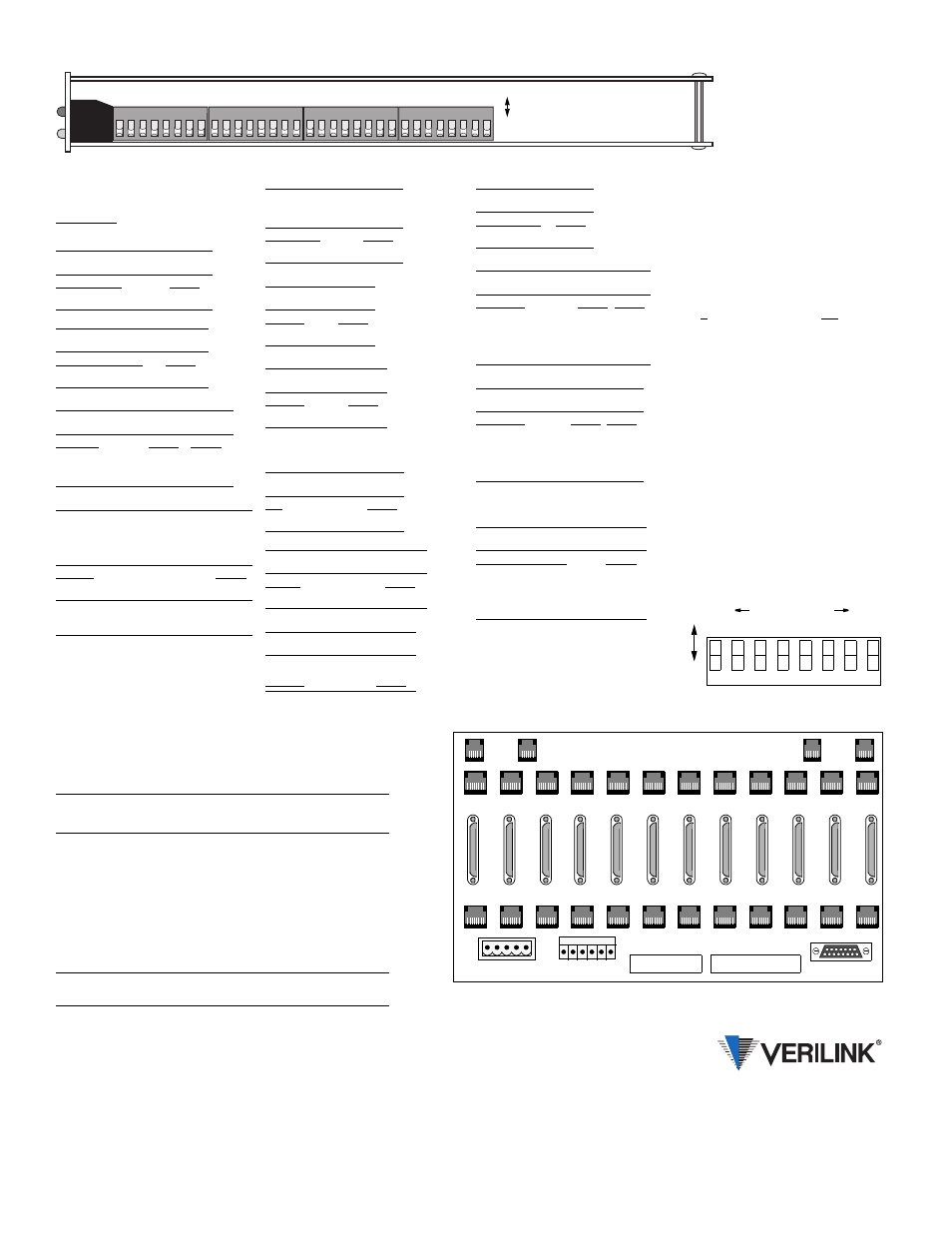
1 2 3 4 5 6 7 8
1 2 3 4 5 6 7 8
1 2 3 4 5 6 7 8 1 2 3 4 5 6 7 8
Switch 1
Switch 2
Switch 3
Switch 4
Do
w
n
Up
Top-Edge View of the PRISM 4051
T1 DTE
1
2
3
4
5
6
7
8
9
10
11
12
( B )
NMS
IN
( B )
NMS
OUT
12
HIGH SPEED DTE
11
10
9
8
7
6
5
4
3
2
1
T1 NET
TB1
TB2
ENET
( A )
NMS
IN
( A )
NMS
OUT
TB1
TB2
Rear Panel of the Verilink 1051-2 Chassis
1
2
3
4
5
6
7
8
9
10
11
12