Watson-Marlow 313F User Manual
Page 4
4
313U automatic operation
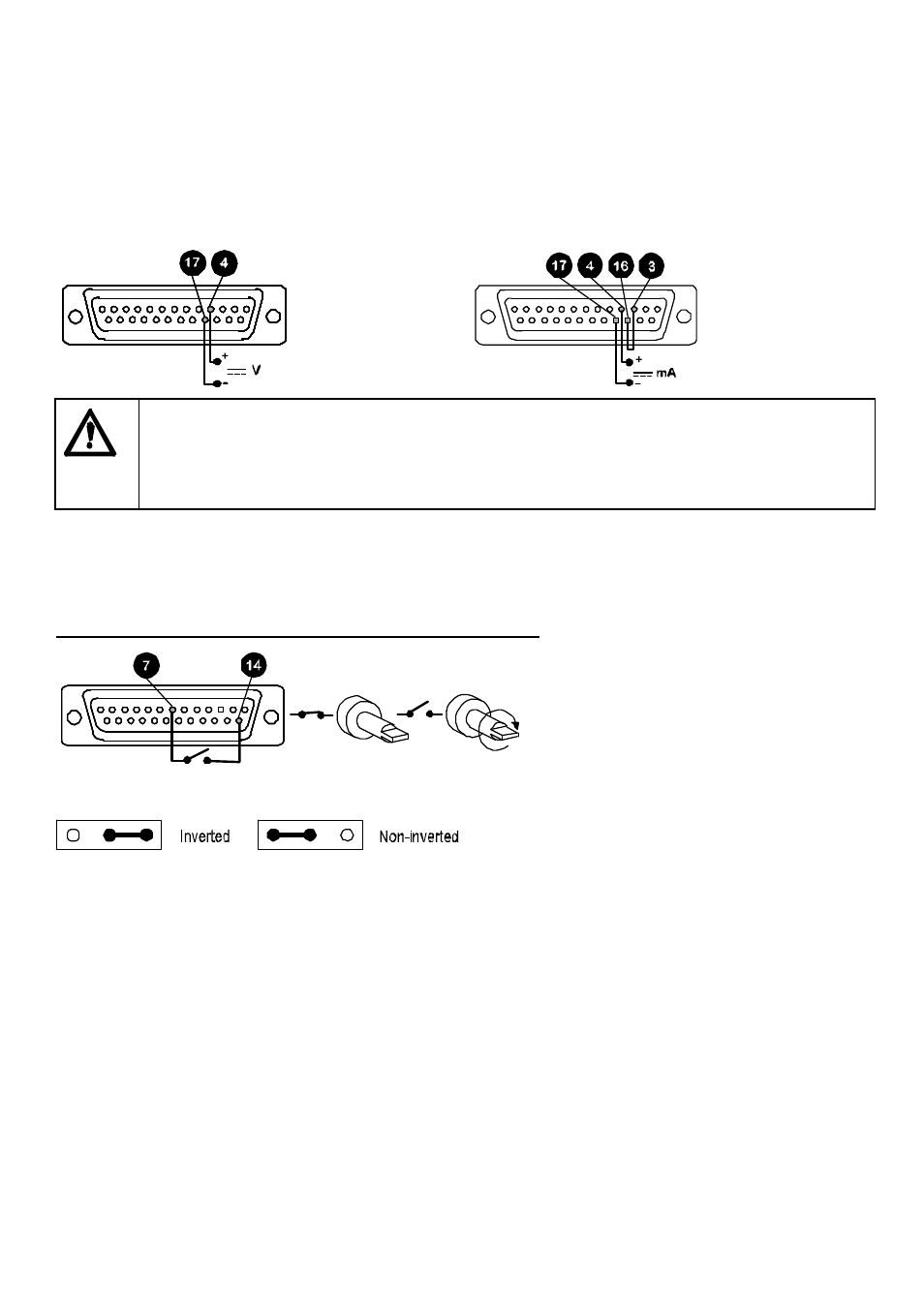
For the pump to be controlled by a process signal, the auto volts/manual/auto current (V M I) slider switch on the rear
panel should be set to either auto volts or auto current depending upon the type of control signal to be used. Ensure that
the mains switch on the rear panel is off. The process signal must be connected to the 25-way Dee plug provided, which
must be inserted in the rear panel 25-way Dee connector. The pump is controllable by an analogue process signal of up
to 0 to 10V or 4 to 20mA. The pump will provide an increasing flow rate for rising control signal (non-inverted response ).
Voltage signal
Input impedance 220 kohms. Maximum
voltage signal 10V
Current signal
Input impedance 250 ohms
Never apply mains voltage across any pins on the 25D socket. Up to 10V may be applied across pins
4 and 17, but no voltage should be applied across other pins. Permanent damage, not covered by
warranty may result in both instances. Do not use the mains power switch to control the pump for a
high repetition of stop/starts. The auto-control facility should be used.
When setting the drive control mode with the V M I switch ensure that power to the drive is switched
off using the mains switch on the rear panel.
Remote control
Stop/Start
Connect remote switch between pins 7 and 14 of the 25 pin socket. Close contact to stop the pump, open to run. With
no connection, the pump will default to running. A remote stop/start signal will control the pump whilst running under
manual operation.
A TTL compatible logic input (Low 0V High 5V ) may be applied to pin 7.
To invert the response to the signal input move the remote stop signal inverter link (see 313 "U" upgrade card, item 4,
LK2) to the inverted pin positions on the signal inverter link block.
Note: When the pump is running in either direction and is stopped remotely, it will freewheel to a stop.