Watson-Marlow 313F User Manual
Page 5
5
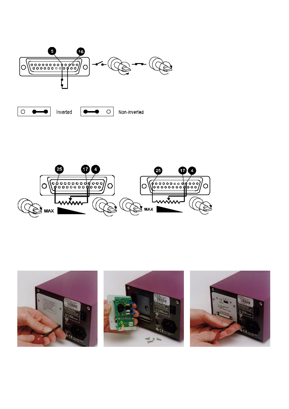
Direction
The remote direction facility operates with the front panel direction switch set in the anti-clockwise direction
only. Connect remote switch between pins 5 and 16. Open switch for anti-clockwise rotation, close for clockwise
rotation. With no connection, the pump will default to anti-clockwise
To invert the response to the signal input move the remote direction signal inverter link LK1 (see 313 "U" upgrade card,
item 6, LK1) to the inverted pin positions on the signal inverter link block.
Note: When the front panel switch is set to CCW rotation, the drive rotates according to the remote switch direction set
by LK1. When the front panel switch is set to CW rotation the remote switch is inhibited.
Speed
A remote potentiometer with a nominal value of between 1K and 2K with a minimum of 0.25W should be wired as shown.
When using a remote potentiometer, do not apply a voltage/current control input signal at the same time. Set the drive
control mode to auto volts (0-10V). Ensure that when changing the drive control mode, power to the drive is switched off
using the rear panel mains switch.
Note: As the remote potentiometer utilises the 0-10V range the speed response is only over
10
/
12
ths
of the potentiometer's
electrical travel. The signal overload illuminates at this point and there is no further increase in speed.
313U upgrade card
To upgrade the manually controllable 313S/D into a remote or 0-10V/4-20mA analogue controllable 313U/D a 313U
upgrade card will be required (part number 039.3001.U00). To install the "U" card, undo the four M3 screws on the drive
rear panel "S" version cover plate and remove. Slot the 313U upgrade card into the rear panel recess, drop down to align
the DIN edge connectors and push into position. Replace the four M3 screws on the card to secure it firmly to the rear
panel.