Sat 3p installation guide, Sat 3p pulse input and components – WattMaster WCC III part 19 User Manual
Page 4
WCC III Technical Guide
18-2
18. SAT 3P INSTALLATION GUIDE
When used in conjunction with the WCC III system, the SAT III
controllers and SAT 3P controllers are capable of recording energy
demand, energy consumption, as well as sub-metering, and then
automated logging of tenant power usage. Sophisticated turning
OFF of high usage energy equipment when there is high energy peak
demand time is also possible with what is called “Shed and Restore
Program” via the WCC III system. This can be accomplished by
using a pulse meter on the building incoming power that outputs a
binary contact closure to a pulse meter input on a SAT III or SAT
3P controller. Then, by making global analog and/or global binary
determinations, make an intelligent decision as to what equipment
to keep on and what equipment to turn off.
The binary outputs from the pulse meter(s) must be of the isolated
output type. They can be of the optically coupled open-collector
current sink transistor output type or an actual dry contact type of
output. Please consult with WattMaster Controls if you have any
questions at all about the type of connection from the Pulse Meter
to the SAT 3P controller(s).
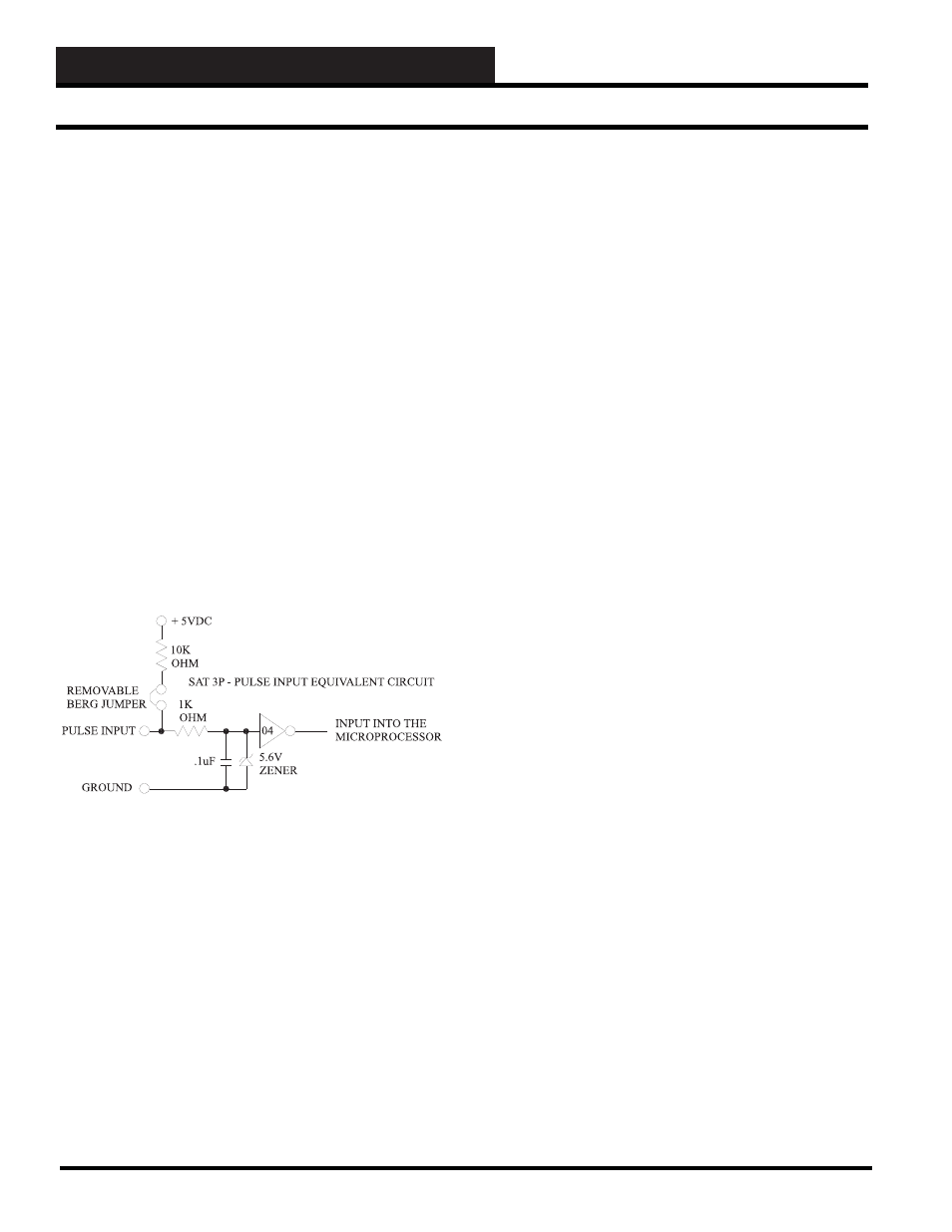
The binary input circuit equivalent of the SAT 3P controller is
summarized in Figure 18-2:
The two position Removable Berg Jumper on each of the eight
Pulse Inputs on the SAT 3P controller are normally connected.
These Removable Berg Jumpers connect a +5 volt DC pull up via
a 10K ohm current limit resistor to each of the eight Pulse Inputs
on the SAT 3P controller. These Removable Berg Jumpers are to
be removed only if an external voltage source is to be used with the
pulse meter output.
WattMaster Controls-approved pulse meter with isolated outputs
are E-Mon D-Mon Class 2000 Three-Phase kWh or KWh/Demand
meter with the optional E-Mon D-Mon P2 Pulser output module.
The E-Mon D-Mon P2 Pulser output module is an optically coupler
interface device that allows the Class 2000 kWh or KWh/Demand
meter to be connected to an energy/building management system
(EMS) for the purpose of data-gathering and/or load control.
The pulse width and value are selected using the 2 DIP switches
and can be tailored to fi t you specifi c requirements in the fi eld. A
modular plug connects the P2 Pulser output module to the E-Mon
D-Mon meter. A two position screw terminal block provides an
easy connection to the EMS (SAT 3P controller). An LED on the
P2 Pulser output module shows the rate and duration of the pulse
output that is going to the EMS (SAT 3P Controller). The P2 Pulser
output module has an output operation of 4.5 to 28 volts DC that is
to be supplied by the EMS. (SAT 3P Controller)
Please refer to Figure 18-3 for referencing the following
components of the SAT 3P controller:
Communications Terminal Block (Labeled TB2)
The SAT 3P connects to the WCC III system the same way as other
SAT III, and SAT 3C/D,F controllers do via a proprietary RS-485
network. The physical network layer consists of a two -wire twisted
pair with shield wire. WattMaster Controls can provide a detailed
specifi cation for this wire as well as provide 500’ or 1000’ spools
of this wire. All terminated wiring is by three position unpluggable
terminal blocks or single unpluggable ¼ inch spade connections.
When terminating wire, connect “R” to “R”, “T” to “T”, and
“SHLD” TO “SH” throughout the whole WCC III system.
Comm LED
This LED is tied to the “DIR” line of the RS-485 driver chip
(LT1785 – WM Part # ID001785). It will slightly blink on receipt
of a communications packet.
Power In Terminal Block (Labeled TB3)
Connect 24VAC and Ground from a transformer.
Warning:
Observe Polarity
. We recommend using a separate transformer,
but as long as the same polarity is used for 24VAC and GND on
all Satellite connections, then multiple Satellite controllers can be
powered off of a single transformer, as long as you do not exceed
the VA rating of the transformer. Use a self-fusing transformer or
use a suitable sized fuse for your transformer that accounts for the
total VA draw. The Sat 3P draws 3 VA, SAT III draws 15VA, and
the SAT 3C/D/F draws 10VA.
Power LED
This LED is tied to the +5 Volt DC power supply of the SAT 3P
controller. This LED should always be “ON” and never blink.
Figure 18-2: Schematic showing the SAT 3P Pulse
Input equivalent circuit multiplied times eight circuits
SAT 3P Pulse Input and Components