Westermo ODW-730-F1 User Manual
Page 17
17
6651-2241
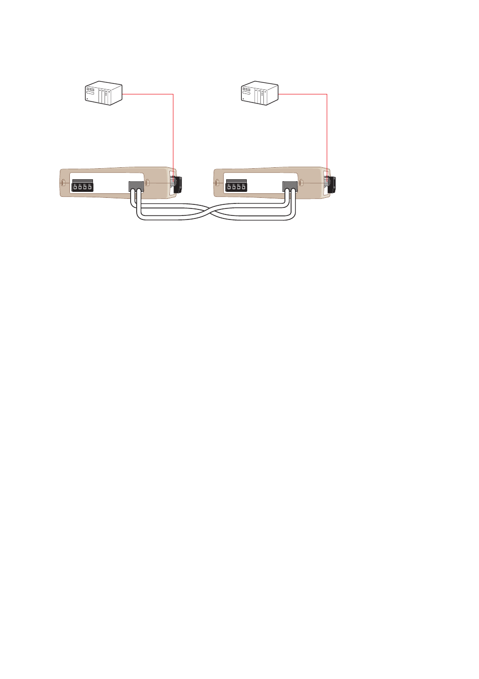
… Make sure that DIP-switches S1:8 and S2:2 – S2:8 are set to factory default positions.
(I.e. S1:8 OFF, S2:2 OFF, S2:3 ON and S":4 – S2:8 OFF).
… Configure both ODW-730-F1 units for the correct speed and data format using DIP-
switches S1:1 – S1:7.
… Select RS-485 2- or 4-wire mode using DIP-switch S2:1 (OFF = 2-wire, ON = 4-wire).
… Enable the RS-485 termination / fail safe if required using DIP-switches S3:1 – S3:4
(S3:1 asnd S3:2 = 4-wire termination, S3:3 and S3:4 = 2-wire connection.)
… Connect the fibre link between the ODW-730-F1.
… Connect the power supply to both ODW-730-F1.
… After a few seconds the fibre link should be in operation, indicated by an active CH1
LED.
… Connect the serial cables from PLC master and slave to respective ODW-730-F1.
… Frames from PLC master that are correctly received in the ODW-730-F1 will be
indicated by flashing TD LED.
… Frames that are received via the fibre link will be transmitted to the PLC slave
and indicated by flashing RD LED.
… Replies from slave to master will be transferred and indicated in the opposite way.
… The point-to-point application is up and running.
POWER
CH 1
COM +VA +VB COM
POWER
CH 1
COM +VA +VB COM
TX
RX
TX
RX
Start up guide, point-to-point application
Follow the steps below to get the unit up and running in a simple application.
Master
Slave