Alarm connections (opto link monitor), Sg td rd, Max 30v, 80 ma relay – Westermo LD-64 User Manual
Page 21: Rs-422 equipment r, Rs-485 equipment t
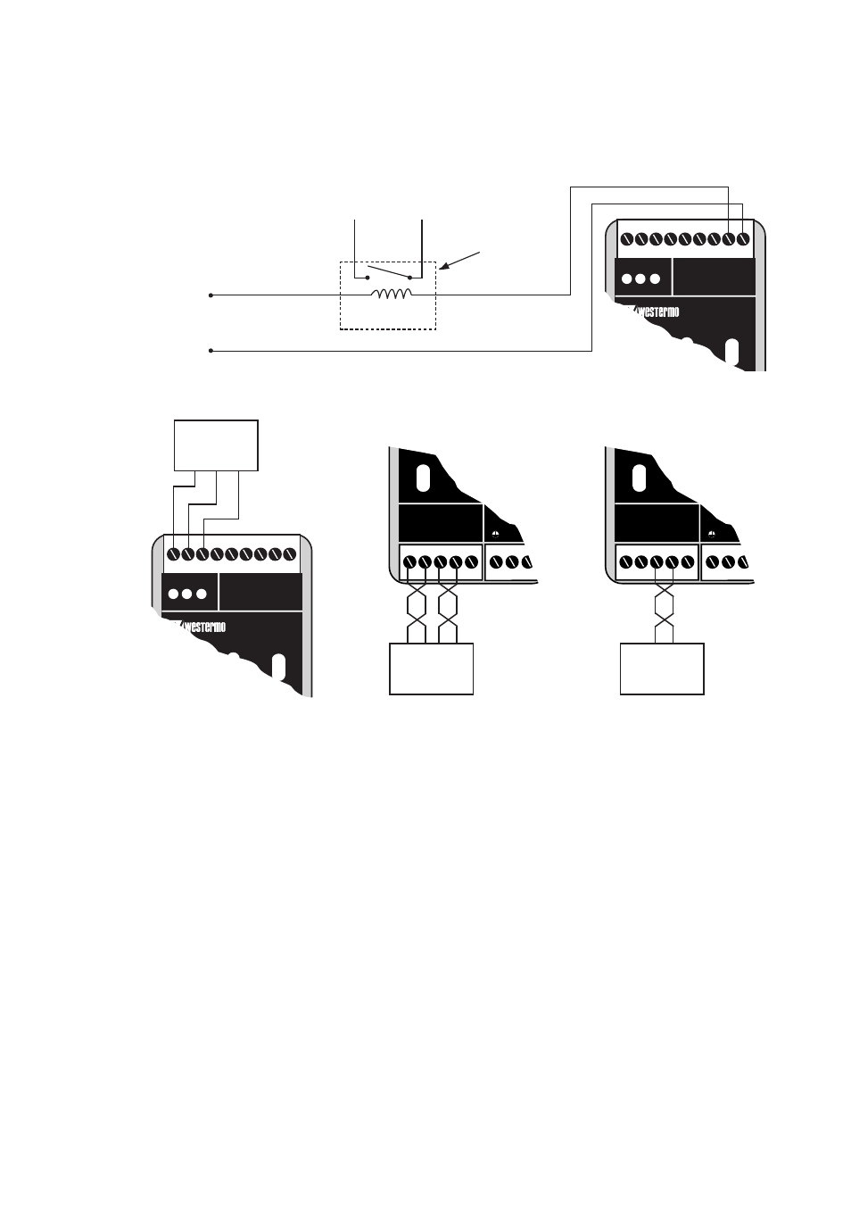
The alarm connection can for example be used
to control an external relay.
21
6073-2002
LD-64
Rx1
Rx2
TD RD
C
E
PWR
OPTO LINK MONITOR
Ch1
C
E
Ch2
SG TD RD
RS-232/V.24
DTE-equipment
*) The designations T+, T–, R+, R– are not standardised and may vary between different
manufactures. The first step in fault finding is to reverse the cables (swap T+ with T–
and/or R+ with R–). Please note that this should be done only at one end!
LD-64
Rx1
Rx2
TD RD
C
E
PWR
OPTO LINK MONITOR
Ch1
C
E
Ch2
Max 30V, 80 mA
Relay
In this example only channel 2 is connected. Under normal operation channel 1 and channel 2
should be connected.
+
–
Alarm connections (Opto Link Monitor)
Upon failure the circuit between the contacts C and E is closed.
Please note that the maximum allowed voltage/current is 30 V / 80 mA.
1
2
3
4
5
L
N
RS-422/485
POWER
R+
Rx2
Tx1
Tx2
R- T+
T-
1
2
3
4
5
L
N
RS-422/485
POWER
R+
Rx2
Tx1
Tx2
R- T+
T-
R
+
RS-422
equipment
R
–
T
+
T
–
RS-485
equipment
T
+
T
–
*
*