Westermo MDW-45 User Manual
Page 13
13
6617-2203
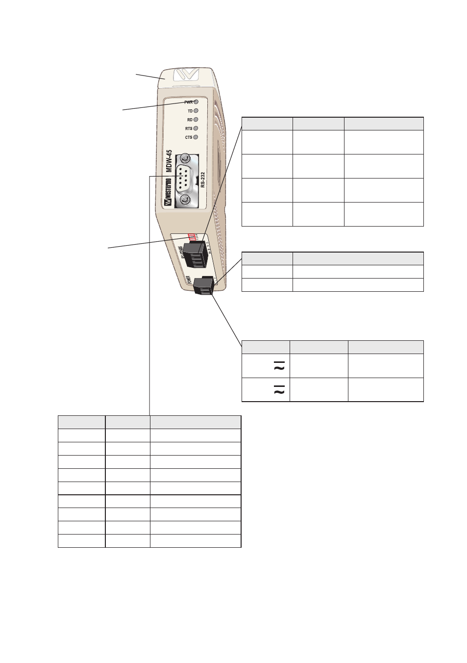
LED indicators
(for details see page 8)
S2 DIP-switch
Termination
(for details see page 11)
S1 DIP-switch under lid
(for details see page 10)
Power connection, HV
screw terminal
Locations of Interface ports, LED`s and DIP-switches
Power connection, LV
screw terminal
RS-232 (DCE)
RS-422/485 interface
screw terminal
Railway installation
close to the rails
(RS-232, RS-422/485)
For a cable located inside 3 m boundary and
connected to this port, the use of shielded
cable is recommended, this to minimize the
risk of interference. The cable shield should
be properly connected (360°) to an earthing
point within 1 m from this port. This earth-
ing point should have a low impedance con-
nection to the conductive enclosure of the
apparatus cabinet, or similar, where the unit
is built-in. This conductive enclosure should
be connected to the earthing system of an
installation and may be directly connected to
the protective earth.
4-position Direction* Description
No. 1
In
R+
line RS-422
No. 2
In
R–
line RS-422
No. 3
In/Out
T+
line RS-422/485
No. 4
In/Out
T–
line RS-422/485
2-position Description
No. 1
0 VDC
No. 2
12 – 48 VDC
2-position
Description Product marking
No. 1
AC: Neutral
DC: –Voltage
N/–
No. 2
AC: Line
DC: +Voltage
L/+
9-position Direction Description
No. 1
–
No. 2
Out
Received Data (RD)
No. 3
In
Transmitted Data (TD)
No. 4
–
No. 5
–
Signal Ground (SG)
No. 6
Out
Data Set Ready (DSR)
No. 7
In
Request To Send (RTS)
No. 8
Out
Clear To Send (CTS)
No. 9
–