Unit specific description, Field of application – Westermo MDW-45 User Manual
Page 17
17
6617-2203
Unit specific description
When the converter is set to data-control mode the transmitter is activated by data on
TD (RS-232).The time the transmitter stays active corresponds to one character-time
plus the turning time for the set data rate and number of bits. If more data arrives on
TD before the turning time has expired the transmitter stays active for an additional
one character time and so on. In RTS-control mode the transmitter is activated by the
RS-232 RTS-signal. In this mode the dip-switches for data rate and number of bits have
no effect. The LED indicators show the status of the data signals. The fail-safe termination
ensures that the signal level at the receiver is in ‘mark state’ (differential>0.2 Volts) when
there is no data on the RS-485 bus. Full duplex is only possible if 4-wires are used.
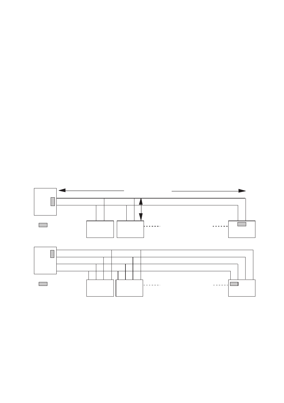
Field of application
RS-422 and RS-485 were both designed for multidrop applications. When a system is
installed it should always form a bus structure (see diagrams). Star shaped networks
should never be created; there are other Westermo products that can be used to create
star net applications. To install a system according to the RS-422/485 specification it is
very important that the line is terminated at the correct points. The recommendation is
to terminate the receiver on the master unit and the final bus slave unit. See diagrams for
details of how this is done with RS-485 (2-wire) and RS-422 (4-wire).
=Termination
Max 32 connections
Max 1 200 metres
Max 0.3 metre
=Termination
Max 32 connections
T+
T–
T+
T–
T+
T–
T+
T–
R+
R–
T+
T–
R– R+
R+
T–
T–
T+
R– R+ T– T+
T+
R–
N.B. R+/R–, T+/T– definitions are not standard, it can help to shift + and –
if the unit does not work.